HT46F46E/HT46F47E/HT46F48E/HT46F49E
A
u
t
o
m
a
t
i
c
a
l
l
y
C
A
l
e
u
a
t
r
o
e
m
d
a
t
b
i
y
c
a
I
l
S
l
y
R
D
i
s
a
b
l
e
d
b
M
a
n
u
a
l
l
y
S
e
t
o
r
C
C
l
e
a
a
n
r
e
b
d
e
b
E
y
n
a
S
b
o
l
f
e
t
d
w
a
M
r
a
e
n
u
a
l
l
y
P
r
i
o
r
i
t
y
E
x
t
e
r
n
a
l
I
n
t
e
r
r
u
p
t
E M
E
E
I
I
H
i
g
h
R
e
q
u
e
s
t
F
l
a
g
E
I
F
T
i
r
m
/
e
E
v
e
n
t
C
o
u
n t
I
e
r
I
n
t
e
r
r
u
p
t
E
E
T
A
I
n
t
e
r
r
u
p
t
R
e
q
u
e
s
t
F
l
a
g
T
F
P
o
l
l
i
n
g
A
/
D
C
o
n
v
e
r
t
e
r
D
I
L o
F
w
I
n
t
e
r
r
u
p
t
R
e
q
u
e
s
t
F
l
a
g
A
D
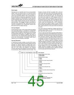
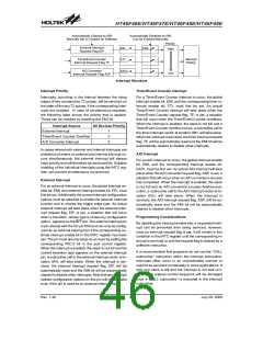
Interrupt Structure
Interrupt Priority
Timer/Event Counter Interrupt
Interrupts, occurring in the interval between the rising
edges of two consecutive T2 pulses, will be serviced on
the latter of the two T2 pulses, if the corresponding inter-
rupts are enabled. In case of simultaneous requests,
the following table shows the priority that is applied.
These can be masked by resetting the EMI bit.
For a Timer/Event Counter interrupt to occur, the global
interrupt enable bit, EMI, and the corresponding timer in-
terrupt enable bit, ETI, must first be set. An actual
Timer/Event Counter interrupt will take place when the
Timer/Event Counter request flag, TF, is set, a situation
that will occur when the Timer/Event Counter overflows.
When the interrupt is enabled, the stack is not full and a
Timer/Event Counter overflow occurs, a subroutine call to
the timer interrupt vector at location 08H, will take place.
When the interrupt is serviced, the timer interrupt request
flag, TF, will be automatically reset and the EMI bit will be
automatically cleared to disable other interrupts.
Interrupt Source
External Interrupt
All Devices Priority
1
2
3
Timer/Event Counter Overflow
A/D Converter Interrupt
In cases where both external and internal interrupts are
enabled and where an external and internal interrupt oc-
curs simultaneously, the external interrupt will always
have priority and will therefore be serviced first. Suitable
masking of the individual interrupts using the INTC reg-
ister can prevent simultaneous occurrences.
A/D Interrupt
For an A/D interrupt to occur, the global interrupt enable
bit, EMI, and the corresponding interrupt enable bit,
EADI, must be first set. An actual A/D interrupt will take
place when the A/D converter request flag, ADF, is set, a
situation that will occur when an A/D conversion process
has completed. When the interrupt is enabled, the stack
is not full and an A/D conversion process finishes exe-
cution, a subroutine call to the A/D interrupt vector at lo-
cation 0CH, will take place. When the interrupt is
serviced, the A/D interrupt request flag, ADF, will be au-
tomatically reset and the EMI bit will be automatically
cleared to disable other interrupts.
External Interrupt
For an external interrupt to occur, the global interrupt en-
able bit, EMI, and external interrupt enable bit, EEI, must
first be set. Additionally the correct interrupt configuration
options must be selected to enable the external interrupt
function and to choose the trigger edge type. An actual
external interrupt will take place when the external inter-
rupt request flag, EIF, is set, a situation that will occur
when a transition, whose type is chosen by configuration
option, appears on the INT line. The external interrupt pin
is pin-shared with the I/O pin PA5 and can only be config-
ured as an external interrupt pin if the corresponding ex-
ternal interrupt enable bit in the INTC register has been
set. The pin must also be setup as an input by setting the
corresponding PAC.5 bit in the port control register.
When the interrupt is enabled, the stack is not full and the
correct transition type appears on the external interrupt
pin, a subroutine call to the external interrupt vector at lo-
cation 04H, will take place. When the interrupt is ser-
viced, the external interrupt request flag, EIF, will be
automatically reset and the EMI bit will be automatically
cleared to disable other interrupts. Note that any pull-high
resistor configuration options on this pin will remain valid
even if the pin is used as an external interrupt input.
Programming Considerations
By disabling the interrupt enable bits, a requested inter-
rupt can be prevented from being serviced, however,
once an interrupt request flag is set, it will remain in this
condition in the INTC register until the corresponding in-
terrupt is serviced or until the request flag is cleared by a
software instruction.
It is recommended that programs do not use the ²CALL
subroutine² instruction within the interrupt subroutine.
Interrupts often occur in an unpredictable manner or
need to be serviced immediately in some applications. If
only one stack is left and the interrupt is not well con-
trolled, the original control sequence will be damaged
once a ²CALL subroutine² is executed in the interrupt
subroutine.
Rev. 1.40
46
July 28, 2009

 HOLTEK [ HOLTEK SEMICONDUCTOR INC ]