HT36F2
All data memory areas can handle arithmetic, logic, in-
crement, decrement and rotate operations directly. Ex-
cept for some dedicated bits, each bit in the data
memory can be set and reset by the ²SET [m].i² and
²CLR [m].i² instructions, respectively. They are also indi-
rectly accessible through Memory pointer registers
(MP0:01H, MP1:03H).
Status Register - STATUS
This 8-bit register (0AH) contains the zero flag (Z), carry
flag (C), auxiliary carry flag (AC), overflow flag (OV),
power down flag (PDF) and Watchdog time-out flag
(TO). It also records the status information and controls the
operation sequence.
With the exception of the TO and PDF flags, bits in the
status register can be altered by instructions like any
other register. Any data written into the status register
will not change the TO or PDF flags. In addition it should
be noted that operations related to the status register
may give different results from those intended. The TO
and PDF flags can only be changed by system power
up, Watchdog Timer overflow, executing the ²HALT² in-
struction and clearing the Watchdog Timer.
Indirect Addressing Register
Location 00H and 02H are indirect addressing registers
that are not physically implemented. Any read/write op-
eration of [00H] and [02H] access data memory pointed
to by MP0 (01H) and MP1 (03H) respectively. Reading
location 00H or 02H directly will return the result 00H.
And writing directly results in no operation.
The function of data movement between two indirect ad-
dressing registers, is not supported. The memory
pointer registers, MP0 and MP1, are 8-bit register which
can be used to access the data memory by combining
corresponding indirect addressing registers.
The Z, OV, AC and C flags generally reflect the status of
the latest operations.
In addition, on entering the interrupt sequence or exe-
cuting a subroutine call, the status register will not be
automatically pushed onto the stack. If the contents of
status are important and the subroutine can corrupt the
status register, the programmer must take precautions
to save it properly.
Accumulator
The accumulator closely relates to ALU operations. It is
mapped to location 05H of the data memory and it can
operate with immediate data. The data movement be-
tween two data memory locations must pass through
the accumulator.
Interrupt
The HT36F2 provides two internal timer counter inter-
rupts on each bank. The Interrupt Control register
(INTC;0BH) contains the interrupt control bits that sets
the enable/disable and the interrupt request flags.
Arithmetic and Logic Unit - ALU
This circuit performs 8-bit arithmetic and logic operation.
The ALU provides the following functions:
Once an interrupt subroutine is serviced, all other inter-
rupts will be blocked (by clearing the EMI bit). This
scheme may prevent any further interrupt nesting. Other
interrupt requests may occur during this interval but only
the interrupt request flag is recorded. If a certain inter-
rupt needs servicing within the service routine, the pro-
grammer may set the EMI bit and the corresponding bit
of the INTC to allow interrupt nesting. If the stack is full,
the interrupt request will not be acknowledged, even if
·
·
·
·
·
Arithmetic operations (ADD, ADC, SUB, SBC, DAA)
Logic operations (AND, OR, XOR, CPL)
Rotation (RL, RR, RLC, RRC)
Increment & Decrement (INC, DEC)
Branch decision (SZ, SNZ, SIZ, SDZ ....)
The ALU not only saves the results of a data operation but
can also change the status register.
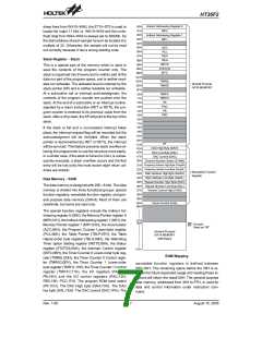
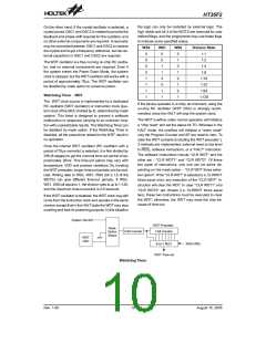
Bit No.
Label
Function
C is set if an operation results in a carry during an addition operation or if a borrow does not
take place during a subtraction operation; otherwise C is cleared. Also it is affected by a ro-
tate through carry instruction.
0
C
AC is set if an operation results in a carry out of the low nibbles in addition or no borrow from
the high nibble into the low nibble in subtraction; otherwise AC is cleared.
1
2
3
AC
Z
Z is set if the result of an arithmetic or logical operation is zero; otherwise Z is cleared.
OV is set if an operation results in a carry into the highest-order bit but not a carry out of the
highest-order bit, or vice versa; otherwise OV is cleared.
OV
PDF is cleared by either a system power-up or executing the ²CLR WDT² instruction. PDF
is set by executing the ²HALT² instruction.
4
PDF
TO is cleared by a system power-up or executing the ²CLR WDT² or ²HALT² instruction. TO
is set by a WDT time-out.
5
TO
6~7
¾
Unused bit, read as ²0²
Status (0AH) Register
Rev. 1.00
8
August 15, 2005

 HOLTEK [ HOLTEK SEMICONDUCTOR INC ]