HT36F2
·
·
Output frequency definition
Repeat number definition
The data on BL3~BL0 and FR11~FR0 are used to de-
fine the output speed of the PCM file, i.e. it can be
used to generate the tone scale. When the FR11~FR0
is 800H and BL3~BL0 is 6H, each sample data of the
PCM code will be sent out sequentially.
The repeat number is used to define the address
which is the repeat point of the sample. When the re-
peat number is defined, it will be output from the start
code to the end code once and always output the
range between the repeat address to the end code
(80H) until the volume become close.
When the fOSC is 6.4MHz, the formula of a tone fre-
quency is:
The RE12~RE0 is used to calculate the repeat ad-
dress of the PCM code. The process for setting the
RE12~RE0 is to write the 2¢s complement of the re-
peat length to RE12~RE0, with the highest carry ig-
nored. The HT36F2 will get the repeat address by
adding the RE12~RE0 to the address of the end code,
then jump to the address to repeat this range.
25kHz FR11~ FR0
x
fOUT= fRECORD x
(17-BL3~BL0)
SR
2
where fOUT is the output signal frequency, fRECORD and
SR is the frequency and sampling rate on the sample
code, respectively.
So if a voice code of C3 has been recorded which has
the fRECORD of 261Hz and the SR of 11025Hz, the tone
frequency (fOUT) of G3: fOUT=98Hz.
·
·
·
Volume control
The HT36F2 provides the volume control independ-
ently. The volume are controlled by VR9~VR0 respec-
tively. The chip provides 1024 levels of controllable
volume, the 000H is the maximum and 3FFH is the
minimum output volume.
Can be obtained by using the fomula:
FR11~ FR0
25kHz
98Hz= 261Hz x
x
(17-BL3~BL0)
11025Hz
2
A pair of the values FR11~FR0 and BL3~BL0 can be
determined when the fOSC is 6.4MHz.
The PCM code definition
·
Start address definition
The HT36F2 can only solve the voice format of the
signed 8-bit or 12-bit raw PCM. And the MCU will take
the voice code 80H as the end code.
So each PCM code section must be ended with the
end code 80H.
The HT36F2 provides two address types for extended
use, one is the program ROM address which is pro-
gram counter corresponding with PF value, the other
is the start address of the PCM code.
The ST15~ST0 is used to define the start address of
each PCM code and reads the waveform data from
this location. The HT36F2 provides 16 input data lines
from WA15~WA0, the ST15~ST0 is used to locate the
major 12 bits i.e. WA15~WA5 and the undefined data
from WA4~WA0 is always set as 00000b. In other
words, the WA15~WA0=ST15~ST0´25. So each
PCM code has to be located at a multiple of 32. Other-
wise, the PCM code will not be read out correctly be-
cause it has a wrong start code.
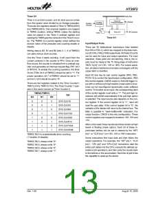
Digital to Analog Converter - DAC
The HT36F2 provides one 16-bit voltage type DAC
device controlled by the MCU or Wavetable Synthe-
sizer for driving the external speaker through an exter-
nal NPN transistor. It is in fact an optional object used
for Wavetable Synthesizer DAC or general DAC, this
is chosen by Mask Option and DAC control register. If
the general DAC is chosen for application, then the
Wavetable Synthesizer is disabled since the DAC is
taken up and controlled by the MCU. If general DAC is
selected, the programmer must write the voice data to
register DAL and DAH to get the corresponding ana-
log data. If Mask Option enables the DAC register and
the SELW, then the following table comes useful.
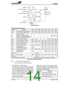
·
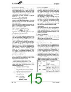
Waveform format definition
The HT36F2 accepts two waveform formats to ensure
a more economical data space. WBS is used to define
the sample format of each PCM code.
¨
WBS=0 means the sample format is 8-bit
Bit No.
Label
Function
¨
WBS=1 means the sample format is 12-bit
The 12-bit sample format allocates location to each
sample data. Please refer to the waveform format
statement as shown below.
Bit7~Bit3
No used
¾
DAON=1: DAC ON
Bit1
DAON
DAON=0: DAC OFF (Default)
8
-
B
i
t
1
B
2
B
3
B
4
B
5
B
6
B
7
B
8
B
SELWR=1, Right Channel
DAC data from Wavetable
SELWR=0, Right Channel
DAC data from MCU (Default)
Bit0
SELWR
A
1
s
a
m
p
l
i
n
g
d
a
t
a
c
o
d
e
;
B
m
e
a
n
s
o
n
e
d
a
t
a
b
y
t
e
.
1
2
-
B
i
t
H
1
M
1
L
2
L
2
H
2
M
3
H
3
M
3
L
A
s
a
m
p
l
i
n
g
d
a
t
a
c
o
d
e
N
o
t
e
:
"
1
H
"
H
i
g
h
N
i
b
b
l
e
"
"
1
1
M
L
"
M
i
d
d
l
e
N
i
b
b
l
e
"
L
o
w
N
i
b
b
l
e
Waveform Format
Rev. 1.00
15
August 15, 2005

 HOLTEK [ HOLTEK SEMICONDUCTOR INC ]