HD44780U
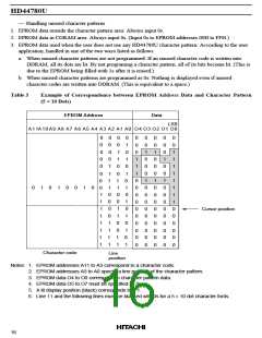
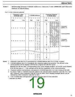
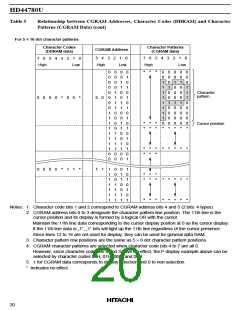
Table 5
Relationship between CGRAM Addresses, Character Codes (DDRAM) and Character
Patterns (CGRAM Data) (cont)
For 5 × 10 dot character patterns
Character Codes
(DDRAM data)
Character Patterns
(CGRAM data)
CGRAM Address
7
6
5
4
3
2
1
0
5
4
3
2
1
0
7
6
5
4 3 2 1 0
High
Low
High
Low
High
Low
0
0
0
0
1
1
0
0
1
1
0
0
1
1
0
0
1
1
0
0
0
*
*
*
0
0
0
0
0
1
0
0
0
1
0
0
0
0
*
0
0
0
1
1
1
0
0
0
0
0
*
0
0
0
0
0
0
0
1
1
1
1
1
1
1
1
0
0
0
0
0
1
1
1
1
0
0
0
0
1
1
1
1
0
0
1
0
1
0
1
0
1
0
1
0
1
0
1
0
1
0
1
0
1
1
1
1
1
1
1
1
0
*
0
0
1
0
0
1
0
0
0
0
*
0
1
0
0
0
1
0
0
0
0
*
Character
pattern
0
0
0
0
*
0
0
*
0 0
*
*
*
*
*
*
Cursor position
*
*
*
*
*
*
*
*
*
*
*
0
0
0
0
*
1
1
*
1 1
1
1
1
1
1
1
1
0
0
0
1
1
1
1
0
1
1
0
0
1
1
1
0
1
0
1
0
1
*
*
*
*
*
*
*
*
*
*
*
*
*
*
*
*
*
*
*
Notes: 1. Character code bits 1 and 2 correspond to CGRAM address bits 4 and 5 (2 bits: 4 types).
2. CGRAM address bits 0 to 3 designate the character pattern line position. The 11th line is the
cursor position and its display is formed by a logical OR with the cursor.
Maintain the 11th line data corresponding to the cursor display positon at 0 as the cursor display.
If the 11th line data is „1“, „1“ bits will light up the 11th line regardless of the cursor presence.
Since lines 12 to 16 are not used for display, they can be used for general data RAM.
3. Character pattern row positions are the same as 5 × 8 dot character pattern positions.
4. CGRAM character patterns are selected when character code bits 4 to 7 are all 0.
However, since character code bits 0 and 3 have no effect, the P display example above can be
selected by character codes 00H, 01H, 08H, and 09H.
5. 1 for CGRAM data corresponds to display selection and 0 to non-selection.
* Indicates no effect.
20

 HITACHI [ HITACHI SEMICONDUCTOR ]