HD44780U
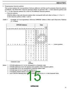
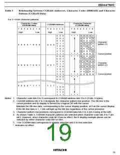
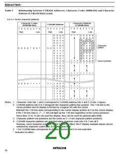
Table 5
Relationship between CGRAM Addresses, Character Codes (DDRAM) and Character
Patterns (CGRAM Data)
For 5 × 8 dot character patterns
Character Codes
Character Patterns
(CGRAM data)
CGRAM Address
(DDRAM data)
7
6
5
4
3
2
1
0
5
4
3
2
1
0
7
6
5
4 3 2 1 0
High
Low
High
Low
High
Low
0
0
0
1
1
0
0
1
1
0
0
1
1
0
0
1
1
0
0
0
*
*
*
1
1
1
1
0
0
1
0
1
0
0
0
1
1
0
1
0
0
0
0
1
1
0
0
0
1
0
1
0
1
0
1
0
0
0
0
0
0
1
1
1
1
0
0
0
0
1
1
1
1
0
0
1
0
1
0
1
0
1
0
1
0
1
0
1
0
1
0
1
1
1
1
1
1
1
0
1
0
1
0
1
0
0
0
0
0
1
0
0
0
0
0
1
1
0
1
0
0
0
0
0
1
1
0
0
0
0
0
1
1
1
1
1
0
Character
pattern (1)
0
0
0
0
0
0
*
0
0
0
1
0
0
0
0
1
0
*
*
*
*
*
*
Cursor position
Character
pattern (2)
0
0
0
*
0
1
0
1
Cursor position
*
*
*
*
*
*
0
0
0
*
1
1
1
1
1
1
1
1
0
0
1
1
0
1
0
1
*
*
*
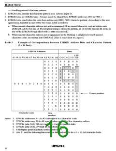
Notes: 1. Character code bits 0 to 2 correspond to CGRAM address bits 3 to 5 (3 bits: 8 types).
2. CGRAM address bits 0 to 2 designate the character pattern line position. The 8th line is the
cursor position and its display is formed by a logical OR with the cursor.
Maintain the 8th line data, corresponding to the cursor display position, at 0 as the cursor display.
If the 8th line data is 1, 1 bits will light up the 8th line regardless of the cursor presence.
3. Character pattern row positions correspond to CGRAM data bits 0 to 4 (bit 4 being at the left).
4. As shown Table 5, CGRAM character patterns are selected when character code bits 4 to 7 are
all 0. However, since character code bit 3 has no effect, the R display example above can be
selected by either character code 00H or 08H.
5. 1 for CGRAM data corresponds to display selection and 0 to non-selection.
* Indicates no effect.
19

 HITACHI [ HITACHI SEMICONDUCTOR ]