FT232BQ USB UART ( USB - Serial) I.C.
7.5 LED Interface
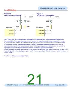
Figure 12
Figure 13
Dual LED Configuration
Single LED Configuration
VCCIO
VCCIO
LED
TX
RX
220R
220R
220R
FT232BQ
FT232BM
FT232BQ
FT232BM
12
12
TXLED#
TXLED#
11
11
RXLED#
RXLED#
The FT232BQ has two IO pins dedicated to controlling LED status indicators, one for transmitted data the other
for received data. When data is being transmitted / received the respective pins drive from tri-state to low in order
to provide indication on the LEDs of data transfer. A digital one-shot timer is used so that even a small percentage
of data transfer is visible to the end user. Figure 12 shows a configuration using two individual LED’s – one for
transmitted data the other for received data. In Figure 13, the transmit and receive LED indicators are wire-OR’ed
together to give a single LED indicator which indicates any transmit or receive data activity.
Another possibility (not shown here) is to use a 3 pin common anode tri-color LED based on the circuit in Figure 13 to
have a single LED that can display activity in a variety of colors depending on the ratio of transmit activity compared to
receive activity.
Note that the LED’s are connected to VCCIO.
DS232BQ Version 1.8
© Future Technology Devices Intl. Ltd. 2005
Page 21 of 25

 FTDI [ FUTURE TECHNOLOGY DEVICES INTERNATIONAL LTD. ]