FT232BQ USB UART ( USB - Serial) I.C.
7.4 UART Interface Configuration
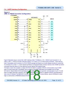
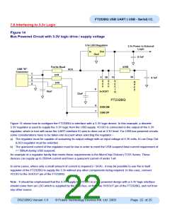
Figure 9
USB <=> RS232 Converter Configuration
FT232BM
FT232BQ
VCC
15
PWREN#
SP213EHCA
DB9-M
10
25
24
23
22
21
20
19
18
16
25
7
11
SLEEP#
TXD
SHDN#
EN
2
3
2
7
8
4
6
1
T1In
T1Out
R4In
TXD
RXD
RTS
CTS
DTR
DSR
DCD
RI
22
20
8
23
1
RXD
R4Out
T3In
RTS#
CTS#
DTR#
DSR#
DCD#
RI#
T3Out
R1In
9
R1Out
T2In
3
6
T2Out
R2In
5
4
R2Out
R3Out
R5Out
T4In
27
16
28
15
26
19
21
12
R3In
9
5
R5In
TXDEN
T4Out
C2+
GND
C1+
0.1uF
0.1uF
0.1uF
14
17
16
13
C1-
V-
C2-
V+
0.1uF
VCC
G
N
D
V
C
C
11
10
0.1uF
VCC
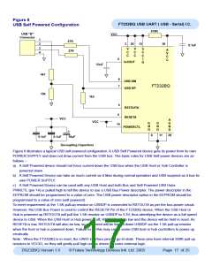
Figure 9 illustrates how to connect the UART interface of the FT232BQ to a TTL – RS232 Level Converter I.C. to
make a USB <=> RS232 converter using the popular “213” series of TTL to RS232 level converters. These devices
have 4 transmitters and 5 receivers in a 28 LD SSOP package and feature an in-built voltage converter to convert the
5v (nominal) VCC to the +/- 9 volts required by RS232. An important feature of these devices is the SHDN# pin which
can power down the device to a low quiescent current during USB suspend mode
The device used in the example is a Sipex SP213EHCA which is capable of RS232 communication at up to 500K
baud. If a lower baud rate is acceptable, then several pin compatible alternatives are available such as Sipex
SP213ECA , Maxim MAX213CAI and Analog Devices ADM213E which are good for communication at up to 115,200
baud. If a higher baud rate is desired, use a Maxim MAX3245CAI part which is capable of RS232 communication at
rates of up to 1M baud. The MAX3245 is not pin compatible with the 213 series devices, also its SHDN pin is active
high so connect this to PWREN# instead of SLEEP#.
DS232BQ Version 1.8
© Future Technology Devices Intl. Ltd. 2005
Page 18 of 25

 FTDI [ FUTURE TECHNOLOGY DEVICES INTERNATIONAL LTD. ]