Package and Pin Listings
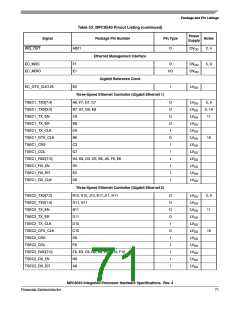
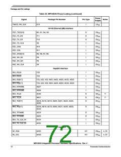
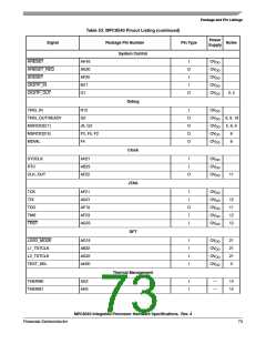
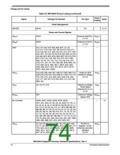
Table 53. MPC8540 Pinout Listing (continued)
Power
Notes
Signal
RESERVED
Package Pin Number
Pin Type
Supply
C1, T11, U11, AF1
—
—
15
13
SENSEVDD
L12
Power for Core
(1.2 V)
VDD
SENSEVSS
VDD
K12
—
—
13
M13, M15, M17, N14, N16, P13, P15, P17, R12,
R14, R16, T13, T15, T17, U12, U14, AH17
Power for Core
(1.2 V)
VDD
Notes:
1.All multiplexed signals are listed only once and do not re-occur. For example, LCS5/DMA_REQ2 is listed only once in the
Local Bus Controller Interface section, and is not mentioned in the DMA section even though the pin also functions as
DMA_REQ2.
2.Recommend a weak pull-up resistor (2–10 kΩ) be placed on this pin to OVDD
.
3.This pin must always be tied to GND. .
4.This pin is an open drain signal.
5.This pin is a reset configuration pin. It has a weak internal pull-up P-FET which is enabled only when the MPC8540 is in
the reset state. This pull-up is designed such that it can be overpowered by an external 4.7-kΩ pull-down resistor. If an
external device connected to this pin might pull it down during reset, then a pull-up or active driver is needed if the signal
is intended to be high during reset.
6.Treat these pins as no connects (NC) unless using debug address functionality.
7.The value of LA[28:31] during reset sets the CCB clock to SYSCLK PLL ratio. These pins require 4.7-kΩ pull-up or
pull-down resistors. See Section 15.2, “Platform/System PLL Ratio.”
8.The value of LALE and LGPL2 at reset set the e500 core clock to CCB Clock PLL ratio. These pins require 4.7-kΩ pull-up
or pull-down resistors. See the Section 15.3, “e500 Core PLL Ratio.”
9.Functionally, this pin is an output, but structurally it is an I/O because it either samples configuration input during reset or
because it has other manufacturing test functions. This pin will therefore be described as an I/O for boundary scan.
10.This pin functionally requires a pull-up resistor, but during reset it is a configuration input that controls 32- vs. 64-bit PCI
operation. Therefore, it must be actively driven low during reset by reset logic if the device is to be configured to be a
64-bit PCI device. Refer to the PCI Specification.
11.This output is actively driven during reset rather than being three-stated during reset.
12.These JTAG pins have weak internal pull-up P-FETs that are always enabled.
13.These pins are connected to the VDD/GND planes internally and may be used by the core power supply to improve
tracking and regulation.
14.Internal thermally sensitive resistor.
15.No connections should be made to these pins.
16.These pins are not connected for any functional use.
17.PCI specifications recommend that a weak pull-up resistor (2–10 kΩ) be placed on the higher order pins to OVDD when
using 64-bit buffer mode (pins PCI_AD[63:32] and PCI_C_BE[7:4]).
18.Note that these signals are POR configurations for Rev. 1.x and notes 5 and 9 apply to these signals in Rev. 1.x but not
in later revisions.
19 If this pin is connected to a device that pulls down during reset, an external pull-up is required to drive this pin to a logic
–1 state during reset.
20.Recommend a pull-up resistor (~1 KΩ) b placed on this pin to OVDD
.
21.These are test signals for factory use only and must be pulled up (100 Ω - 1 kΩ) to OVDD for normal machine operation.
22.If this signal is used as both an input and an output, a weak pull-up (~10 kΩ) is required on this pin.
MPC8540 Integrated Processor Hardware Specifications, Rev. 4
Freescale Semiconductor
75

 FREESCALE [ Freescale ]