FUNCTIONAL DEVICE OPERATION
OPERATIONAL MODES
• Max dwell time
The Max Dwell gate turn off signal is a logically ANDed
with the Soft Shutdown bit to activate a Low-voltage Active
Clamp (See Figure 9).
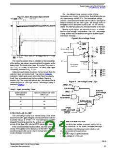
Soft Shutdown is designed to prevent an ignition spark
while turning off the external IGBT. The Low-voltage Clamp
is activated to provide the mechanism for a soft shutdown.
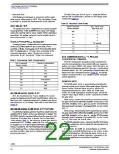
Table 10. Maximum Dwell Timer
GAIN SELECT BIT
Spark Command
Bit<b11,b10,b9>
MAX Dwell Timer
MaxDwell (ms)
The ignition coil current comparators are used to compare
the programmed NOMI and MAXI DAC value with voltage
across the external current sense resistor. When selecting a
gain of two, the ignition coil current sense resistor must be
reduced from 40mΩ to 20mΩ.
000
001
010
011
100
101
110
111
2
4
8
16
OVERLAPPING DWELL ENABLE BIT
32 (default)
Overlapping dwell occurs when two or more ignition mode
drivers are commanded ON at the same time. In this
condition, with the Overlapping Dwell Bit enabled the MAXI
DAC threshold value is increased as a percentage of the
nominal programmed value. The percent increase is
determined by bit 5 through bit 7 of the DAC Command.
64
64
64
DAC COMMAND (DIGITAL TO ANALOG
CONVERSION COMMAND)
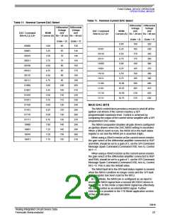
Table 9. Overlapping Dwell Compensation
The DAC Command is an ignition mode command that
sets the nominal ignition coil current (NOMI) and maximum
ignition coil current (MAXI) DAC values. Bits 0 through 4 set
the NOMI threshold value and, bits 8 through 11 set the MAXI
threshold values. The DAC command and default values are
listed in the SPI Command Summary Table 20. The NOMI
output is used by the MCU as a variable in dwell and spark
control algorithms.
DAC Command
Bits<b7,b6,b5>
Overlap Compensation
(%)
000
001
010
011
100
101
110
111
0%
7%
15%
24%
35% (default)
47%
NOMI DAC BITS
The NOMI output signal is generated by comparing the
external current sense resistor differential voltage (Resistor
Sense Positive, Resistor Sense Negative) with the SPI
programmed NOMI DAC value. When the NOMI event
occurs, the NOMI output pin is asserted (High). The NOMI
output is only a flag to the MCU and it’s output does not affect
the gate driver.
63%
80%
MAXIMUM DWELL ENABLE BIT
Bit 8, the Maximum Dwell Enable bit allows the user to
enable the Maximum Dwell Gate Turnoff Feature. When the
Max Dwell bit is programmed as logic 0 (disabled) the device
will not perform a Low-voltage Clamp due to Max Dwell (See
Figure 9).
When using a 20 mΩ resistor as the current sense resistor,
the gain select of the differential amplifier connected to RSP
and RSN, should be set to a gain of 2, via the SPI Command
Message Spark Command (Command 0100, hex 4), Control
bit 6 =1.
MAXIMUM DWELL GATE TURN OFF FEATURE
When using a 40mΩ resistor as the current sense resistor,
the gain select of the differential amplifier connected to RSP
and RSN, should be set to a gain of 1, via the SPI Command
Message Spark Command (Command 0100, hex 4), Control
bit 6 =0. This is also the default value.
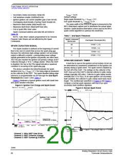
In automotive ignition systems, dwell time is defined as the
duration of time that an ignition coil is allowed to charge. The
MC33810 starts the measure of time from the gate drive ON
command. If the dwell time is greater than the Max Dwell
Timer setting (Table 10), the offending ignition gate driver is
commanded OFF. The Max Dwell Gate Turn Off Feature may
be disabled via bit 8 of the Spark Command. When the
feature is disabled, the Max Dwell fault bits are always logic
0. The Max Dwell Timer feature pertains to Ignition Mode only
and does not affect gate drivers configured as general
purpose gate drivers.
The NOMI output provides a means to alert the MCU when
the ignition coil primary current equals the value programmed
into the NOMI DAC.
In V10 Mode, the NOMI pin is reconfigured as a MAXI
input pin from a third MC33810 device in the system. In this
mode a NOMI input has effectively the same control as an
internal MAXI signal. Further information is provided in the
V10 Mode application section of this data sheet.
33810
Analog Integrated Circuit Device Data
Freescale Semiconductor
22

 FREESCALE [ Freescale ]