Freescale Semiconductor, Inc.
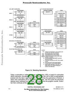
When an interrupt is recognized, the current instruction finishes normally, the return
address (the current value in the program counter) is pushed onto the stack, all of the
CPU registers are pushed onto the stack, and execution continues at the address
specified by the vector for the interrupt. At the end of the interrupt service routine, an
RTI instruction is executed. The RTI instruction causes the saved registers to be pulled
off the stack in reverse order. Program execution resumes at the return address.
There are instructions that push and pull the A and B accumulators and the X and Y
index registers. These instructions are often used to preserve program context. For
example, pushing accumulator A onto the stack when entering a subroutine that uses
accumulator A, and then pulling accumulator A off the stack just before leaving the
subroutine, ensures that the contents of a register will be the same after returning from
the subroutine as it was before starting the subroutine.
3.1.5 Program Counter (PC)
The program counter, a 16-bit register, contains the address of the next instruction to
be executed. After reset, the program counter is initialized from one of six possible
vectors, depending on operating mode and the cause of reset.
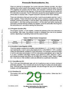
Table 3-1 Reset Vector Comparison
POR or RESET Pin
$FFFE, F
Clock Monitor
$FFFC, D
COP Watchdog
$FFFA, B
Normal
Test or Boot
$BFFE, F
$BFFC, D
$BFFA, B
3.1.6 Condition Code Register (CCR)
This 8-bit register contains five condition code indicators (C, V, Z, N, and H), two inter-
rupt masking bits, (I and X) and a stop disable bit (S). In the M68HC11 CPU, condition
codes are automatically updated by most instructions. For example, load accumulator
A (LDAA) and store accumulator A (STAA) instructions automatically set or clear the
N, Z, and V condition code flags. Pushes, pulls, add B to X (ABX), add B to Y (ABY),
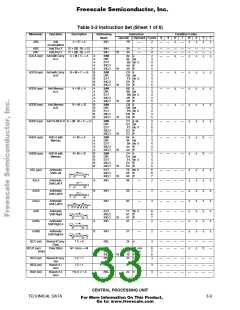
and transfer/exchange instructions do not affect the condition codes. Refer to Table
3-2, which shows what condition codes are affected by a particular instruction.
3.1.6.1 Carry/Borrow (C)
The C bit is set if the arithmetic logic unit (ALU) performs a carry or borrow during an
arithmetic operation. The C bit also acts as an error flag for multiply and divide opera-
tions. Shift and rotate instructions operate with and through the carry bit to facilitate
multiple-word shift operations.
3.1.6.2 Overflow (V)
The overflow bit is set if an operation causes an arithmetic overflow. Otherwise, the V
bit is cleared.
CENTRAL PROCESSING UNIT
TECHNICAL DATA
3-5
For More Information On This Product,
Go to: www.freescale.com

 FREESCALE [ Freescale ]