Data Sheet — MC68HC908MR32 • MC68HC908MR16
Section 12. Pulse-Width Modulator for Motor Control (PWMMC)
12.1 Introduction
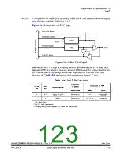
This section describes the pulse-width modulator for motor control (PWMMC,
version A). The PWM module can generate three complementary PWM pairs or six
independent PWM signals. These PWM signals can be center-aligned or
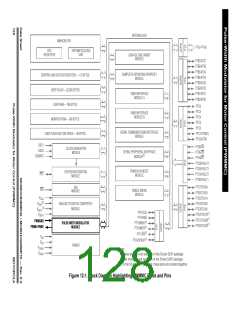
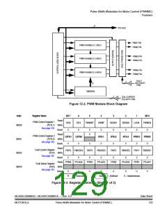
edge-aligned. A block diagram of the PWM module is shown in Figure 12-2.
A12-bit timer PWM counter is common to all six channels. PWM resolution is one
clock period for edge-aligned operation and two clock periods for center-aligned
operation. The clock period is dependent on the internal operating frequency (fOP
)
and a programmable prescaler. The highest resolution for edge-aligned operation
is 125 ns (fOP = 8 MHz). The highest resolution for center-aligned operation is
250 ns (fOP = 8 MHz).
When generating complementary PWM signals, the module features automatic
dead-time insertion to the PWM output pairs and transparent toggling of PWM data
based upon sensed motor phase current polarity.
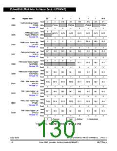
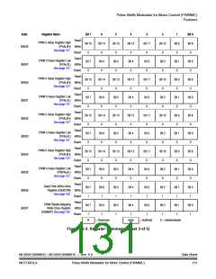
A summary of the PWM registers is shown in Figure 12-3.
12.2 Features
Features of the PWMMC include:
•
•
•
•
•
•
•
Three complementary PWM pairs or six independent PWM signals
Edge-aligned PWM signals or center-aligned PWM signals
PWM signal polarity control
20-mA current sink capability on PWM pins
Manual PWM output control through software
Programmable fault protection
Complementary mode featuring:
–
–
Dead-time insertion
Separate top/bottom pulse width correction via current sensing or
programmable software bits
MC68HC908MR32 • MC68HC908MR16 — Rev. 6.0
MOTOROLA Pulse-Width Modulator for Motor Control (PWMMC)
Data Sheet
127

 FREESCALE [ Freescale ]