Freescale Semiconductor, Inc.
General Description
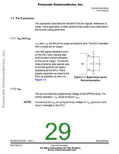
Pin Functions
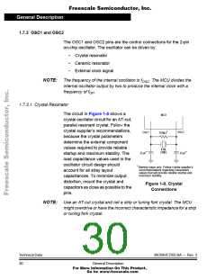
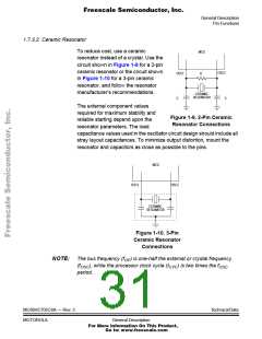
1.7.3.2 Ceramic Resonator
To reduce cost, use a ceramic
MCU
resonator instead of a crystal. Use the
circuit shown in Figure 1-9 for a 2-pin
ceramic resonator or the circuit shown
in Figure 1-10 for a 3-pin ceramic
resonator, and follow the resonator
manufacturer’s recommendations.
OSC2
OSC1
R
CERAMIC
RESONATOR
C
C
The external component values
required for maximum stability and
reliable starting depend upon the
resonator parameters. The load
Figure 1-9. 2-Pin Ceramic
Resonator Connections
.
capacitance values used in the oscillator circuit design should include all
stray layout capacitances. To minimize output distortion, mount the
resonator and capacitors as close as possible to the pins.
MCU
OSC1
OSC2
CERAMIC
RESONATOR
Figure 1-10. 3-Pin
Ceramic Resonator
Connections
NOTE: The bus frequency (fOP) is one-half the external or crystal frequency
(fOSC), while the processor clock cycle (tCYC) is two times the fOSC
period.
MC68HC705C8A — Rev. 3
MOTOROLA
Technical Data
General Description
For More Information On This Product,
Go to: www.freescale.com

 FREESCALE [ Freescale ]