Freescale Semiconductor, Inc.
General Description
1.7.3 OSC1 and OSC2
The OSC1 and OSC2 pins are the control connections for the 2-pin
on-chip oscillator. The oscillator can be driven by:
• Crystal resonator
• Ceramic resonator
• External clock signal
NOTE: The frequency of the internal oscillator is fOSC. The MCU divides the
internal oscillator output by two to produce the internal clock with a
frequency of fOP
.
1.7.3.1 Crystal Resonator
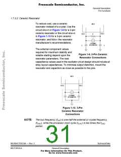
The circuit in Figure 1-8 shows a
crystal oscillator circuit for an AT-cut,
parallel resonant crystal. Follow the
crystal supplier’s recommendations,
because the crystal parameters
determine the external component
values required to provide reliable
startup and maximum stability. The
load capacitance values used in the
oscillator circuit design should
account for all stray layout
MCU
OSC2
OSC1
10 MΩ
XTAL
2 MHz
22 pF
22 pF
Starting value only. Follow crystal supplier’s
recommendations regarding component
values that will provide reliable startup and
maximum stability.
capacitances. To minimize output
distortion, mount the crystal and
capacitors as close as possible to the
pins.
Figure 1-8. Crystal
Connections
NOTE: Use an AT-cut crystal and not a strip or tuning fork crystal. The MCU
might overdrive or have the incorrect characteristic impedance for a strip
or tuning fork crystal.
Technical Data
30
MC68HC705C8A — Rev. 3
General Description
For More Information On This Product,
Go to: www.freescale.com

 FREESCALE [ Freescale ]