PLL Performance Issues
One way to evaluate power consumption is to use a current per MIPS measurement methodology to
minimize specific board effects (i.e., to compensate for measured board current not caused by the DSP).
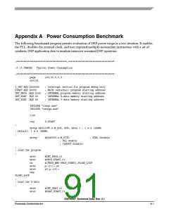
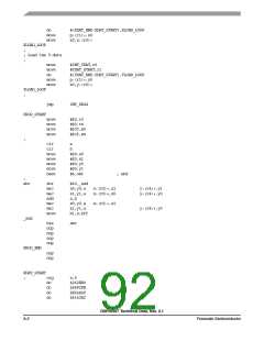
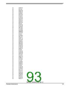
A benchmark power consumption test algorithm is listed in Appendix A, "Power Consumption
Benchmark". Use the test algorithm, specific test current measurements, and the following equation to
derive the current per MIPS value.
I ⁄ MIPS = I ⁄ MHz = (I
– I
) ⁄ (F2 – F1)
typF1
typF2
where:
I
I
= current at F2
typF2
= current at F1
typF1
F2
F1
= high frequency (any specified operating frequency)
= low frequency (any specified operating frequency lower than F2)
NOTE
F1 should be significantly less than F2. For example, F2 could be 66 MHz
and F1 could be 33 MHz. The degree of difference between F1 and F2
determines the amount of precision with which the current rating can be
determined for an application.
5.4
PLL Performance Issues
The following explanations should be considered as general observations on expected PLL behavior.
There is no testing that verifies these exact numbers. These observations were measured on a limited
number of parts and were not verified over the entire temperature and voltage ranges.
5.4.1
Input (EXTAL) Jitter Requirements
The allowed jitter on the frequency of EXTAL is 0.5%. If the rate of change of the frequency of EXTAL
is slow (i.e., it does not jump between the minimum and maximum values in one cycle) or the frequency
of the jitter is fast (i.e., it does not stay at an extreme value for a long time), then the allowed jitter can be
2%. The phase and frequency jitter performance results are only valid if the input jitter is less than the
prescribed values.
DSP56367 Technical Data, Rev. 2.1
5-4
Freescale Semiconductor

 FREESCALE [ Freescale ]