Freescale Semiconductor, Inc.
Inter-IC Bus
15.4 IIC System Configuration
The IIC system uses a Serial Data line (SDA) and a Serial Clock Line
(SCL) for data transfer. All devices connected to it must have open drain
or open collector outputs. Logic “and” function is exercised on both lines
with external pull-up resistors, the value of these resistors is system
dependent.
15.5 IIC Protocol
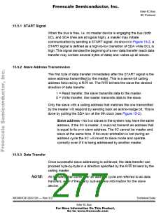
Normally, a standard communication is composed of four parts: START
signal, slave address transmission, data transfer and STOP signal. They
are described briefly in the following sections and illustrated in Figure 15-
2.
MSB
LSB
8
MSB
1
LSB
8
SCL
SDA
1
2
3
4
5
6
7
9
2
3
4
5
6
7
9
AD7 AD6 AD5 AD4 AD3 AD2 AD1 R/W
XXX
D7 D6 D5 D4 D3 D2 D1 D0
Start
Signal
Calling Address
Read/ Ack
Write
Data Byte
No Stop
Ack Signal
Bit
Bit
MSB
1
LSB
MSB
LSB
8
SCL
2
3
4
5
6
7
8
9
1
2
3
4
5
6
7
9
SDA
AD7 AD6 AD5 AD4 AD3 AD2 AD1 R/W
XX
AD7 AD6 AD5 AD4 AD3 AD2 AD1 R/W
Start
Signal
Calling Address
Read/ Ack
Write
Repeated
Start
Signal
New Calling Address
No Stop
Ack Signal
Bit
Read/
Write
Bit
Figure 15-2. IIC Transmission Signals
Technical Data
MC68HC912DG128 — Rev 3.0
Inter-IC Bus
For More Information On This Product,
Go to: www.freescale.com

 FREESCALE [ Freescale ]