•
•
•
•
00 = IRQ disabled (default)
01 = IRQ is priority level 0
10 = IRQ is priority level 1
11 = IRQ is priority level 2
5.6.10.8 ADC B Conversion Complete Interrupt Priority Level
(ADCB_CC IPL)—Bits 1–0
This field is used to set the interrupt priority level for IRQs. This IRQ is limited to priorities 0 through 2.
They are disabled by default.
•
•
•
•
00 = IRQ disabled (default)
01 = IRQ is priority level 0
10 = IRQ is priority level 1
11 = IRQ is priority level 2
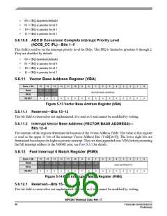
5.6.11 Vector Base Address Register (VBA)
Base + $A
Read
15
0
14
0
13
0
12
11
10
9
8
7
6
5
4
0
3
0
2
0
1
0
0
0
VECTOR BASE ADDRESS
Write
0
0
0
0
0
0
0
0
0
0
0
RESET
Figure 5-13 Vector Base Address Register (VBA)
5.6.11.1 Reserved—Bits 15–13
This bit field is reserved or not implemented. It is read as 0 and cannot be modified by writing.
5.6.11.2 Interrupt Vector Base Address (VECTOR BASE ADDRESS)—
Bits 12–0
The contents of this register determine the location of the Vector Address Table. The value in this register
is used as the upper 13 bits of the interrupt Vector Address Bus (VAB[20:0]). The lower eight bits are
determined based upon the highest-priority interrupt. They are then appended onto VBA before presenting
the full interrupt address to the 56800E core; see Part 5.3.1 for details.
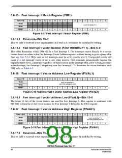
5.6.12 Fast Interrupt 0 Match Register (FIM0)
Base + $B
Read
15
0
14
0
13
0
12
0
11
0
10
0
9
0
8
0
7
0
6
5
4
3
2
1
0
0
0
FAST INTERRUPT 0
Write
RESET
0
0
0
0
0
0
0
0
0
0
0
0
0
0
Figure 5-14 Fast Interrupt 0 Match Register (FIM0)
5.6.12.1 Reserved—Bits 15–7
This bit field is reserved or not implemented. It is read as 0 and cannot be modified by writing.
56F8345 Technical Data, Rev. 17
96
Freescale Semiconductor
Preliminary

 FREESCALE [ Freescale ]