Award-Winning Development Environment
This Digital Signal Controller also provides a full set of standard programmable peripherals that include
one Serial Communications Interface (SCI), one Serial Peripheral Interface (SPI), one Quad Timer, and
2
one Inter-Integrated Circuit (I C) interface. Any of these interfaces can also be used as General Purpose
Input/Outputs (GPIOs).
1.3 Award-Winning Development Environment
TM
Processor Expert
(PE) provides a Rapid Application Design (RAD) tool that combines easy-to-use
component-based software application creation with an expert knowledge system.
The CodeWarrior Integrated Development Environment is a sophisticated tool for code navigation,
compiling, and debugging. A complete set of evaluation modules (EVMs), demonstration board kit and
development system cards will support concurrent engineering. Together, PE, CodeWarrior and EVMs
create a complete, scalable tools solution for easy, fast, and efficient development.
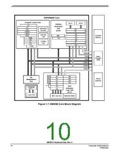
1.4 Architecture Block Diagram
The 56F8014’s architecture is shown in Figure 1-1, Figure 1-2, and Figure 1-3. Figure 1-1 illustrates
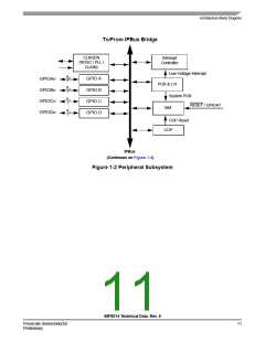
how the 56800E system buses communicate with internal memories and the IPBus Bridge. Figure 1-2 and
Figure 1-3 show the peripherals and control blocks connected to the IPBus Bridge. The figures do not
show the on-board regulator and power and ground signals. They also do not show the multiplexing
between peripherals or the dedicated GPIOs. Please see Part 2 Signal/Connection Descriptions to see
which signals are multiplexed with those of other peripherals.
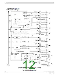
1.4.1
PWM, TMR and ADC Connections
Figure 1-3 shows the over/under voltage connections from the ADC to the PWM and the connections to
the PWM from the TMR and GPIO. These signals can control the PWM outputs in a similar manner to the
over/under voltage control signals. See the 56F801X Peripheral Reference Manual for additional
information.
The PWM_reload_sync output can be connected to the TMR channel 3 input and the TMR channels 2 and
3 outputs are connected to the ADC sync inputs. TMR channel 3 output is connected to SYNC0 and TMR
channel 2 is connected to SYNC1. SYNC0 is the master ADC sync input that is used to trigger ADCA and
ADCB in sequence and parallel mode. SYNC1 is used to trigger ABCB in parallel independent mode.
These are controlled by bits in the SIM Control Register; see Section 6.3.1.
56F8014 Technical Data, Rev. 9
Freescale Semiconductor
Preliminary
9

 FREESCALE [ Freescale ]