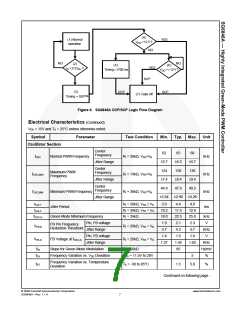
Operation Description
Startup Operation
The turn-on/turn-off thresholds are fixed internally at
16.5V and 10.5V. To enable the SG6846A during
startup, the hold-up capacitor must first be charged to
16.5V through the startup resistor.
If an open-circuit or short-circuit to ground occurs at the
RI pin, the internal protection circuit immediately shuts
down the controller.
Two-level Over-current Protection (OCP)
The cycle-by-cycle current limiting shuts down the PWM
immediately when the switching current is over the
peak-current threshold. Additionally, when the switching
current is higher than the over-current threshold, the
internal counter counts down. When the total
accumulated counting time is more than ~1600ms
(RI = 26kΩ), the controller is latched off and the internal
counter counts up. When the switching current is lower
than the over-current threshold, the internal counter
counts down. When the total accumulated counting
time is more than ~1600ms (RI = 26kΩ), the controller is
latched off.
The hold-up capacitor continues to supply VDD before
energy can be delivered from the auxiliary winding of
the main transformer. The VDD must not drop below
10.5V during this startup process. This UVLO hysteresis
window ensures that the hold-up capacitor can
adequately supply VDD during startup.
The typical startup current is only 8µA, which allows a
high-resistance, low-wattage startup resistor to be used.
For constant output power limit over a universal input-
voltage range, the peak-current threshold is adjusted by
the voltage of the VIN pin. Since the VIN pin is
connected to the rectified AC input line voltage through
the resistive divider, a higher line voltage generates a
higher VIN voltage. The threshold voltage decreases as
the VIN increases, making the maximum output power at
high line input voltage equal to that at low line input.
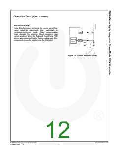
The value of R-C network should not be so large it
affects the power limit (shown in Figure 20). R and C
should put on less than 300Ω and 1000pF, respectively,
to minimize power loss. A 1.5MΩ/0.25W startup resistor
and a 10µF/25V VDD hold-up capacitor are sufficient for
a universal input range.
This two-level OCP protection and up/down counter are
especially designed for SMPS with surge current output,
such as those for printers, scanners, and motor drivers.
Constant Output Power Limit
For constant output power limit over universal input-
voltage range, the peak-current threshold is adjusted by
the voltage of the VIN pin. Since the VIN pin is
connected to the rectified AC input line voltage through
the resistive divider, a higher line voltage generates a
higher VIN voltage. The threshold voltage decreases as
VIN increases, making the maximum output power at
high-line input voltage equal to that at low-line input.
The required operating current has been reduced to
3.7mA, which enables higher efficiency and reduces the
VDD hold-up capacitance requirement.
Brownout Protection
Green-Mode Operation
Since the VIN pin is connected through a resistive
divider to the rectified AC input line voltage, it can also
be used for brownout protection. If the VIN voltage is
less than 0.7V, the PWM output is shut off. If the VIN is
over 0.9V, the PWM output is turned on again. The
hysteresis window for on/off is ~0.2V.
The proprietary green-mode function provides off-time
modulation to continuously decrease the switching
frequency under light-load conditions. Maximum on-time
is limited to provide protection against abnormal
conditions. To further reduce power consumption under
zero-load condition, the PWM oscillator is completely
turned off and the power supply enters burst-mode. This
green mode dramatically reduces power consumption
under light-load and zero-load conditions. Power
supplies using SG6846A can meet restrictive international
regulations regarding standby power consumption.
VDD Over-voltage Protection (OVP)
VDD over-voltage protection is built in to prevent
damage. If VDD is over 23.6V, SG6846A is latched off.
Over-Temperature Protection (OTP)
Oscillator Operation
An external NTC thermistor can be connected from the
RT pin to GND. The impedance of the NTC decreases
at high temperatures. When the voltage of the RT pin
drops below 1.05V, the SG6846A is turned off. For
protection-mode options, see Ordering Information.
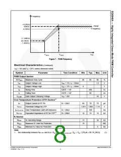
A resistor connected from the RI pin to GND generates
a reference current source, inside the SG6846A, used
to determine the PWM frequency. Increasing the
resistance decreases the amplitude of the current
source and reduces the PWM frequency. Using a 26kΩ
resistor results in a corresponding 65kHz switching
frequency. The relationship between RI and the
switching frequency is:
(2)
1690
f
PWM(kHz)=
RI (kΩ)
© 2008 Fairchild Semiconductor Corporation
SG6846A • Rev. 1.1.4
www.fairchildsemi.com
11

 FAIRCHILD [ FAIRCHILD SEMICONDUCTOR ]