Product Specification
Power Supply Supervisor + Regulator + PWM
SG6105A
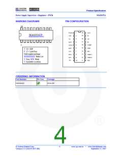
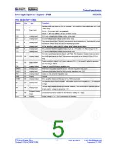
PIN DESCRIPTIONS
Name
Pin Type
Function
Remote on/off logic input for CPU or controller. Turn on/off the PWM output after the 7.5ms
/ 26ms delay.
PSON
1
Logic Input
PSON = 0, the main SMPS is operational.
PSON =1, the main SMPS is off and the latch is reset.
3.3V over-voltage/under-voltage control sense input.
5V over-voltage/under-voltage control sense input.
V33
V5
2
3
Analog Input
Analog Input
Over-power sense input. This pin is connected to driver transformer or the Output of current
transformer. When not in use, this pin should be grounded.
AC fail detection, detect main AC voltage under-voltage and/or failure.
The protection input for negative Output, such as –12V and/or –5V. Trip voltage = 2.1V.
12V over-voltage/under-voltage control sense input.
OPP
4
Analog Input
UVAC
NVP
V12
5
6
7
Analog Input
Analog Input
Analog Input
The totem-pole Output drivers of push-pull PWM. The Output are enabled (low) only when
the NAND gate inputs are high. The maximum duty cycle on an Output (OP1 or OP2) is
46%.
OP1/OP2
9/8
Analog Output
Power-good logic output, 0 or 1 (open-collector). PG = 1, the power is good for operation.
The PG delay is 300ms.
PG
10
Logic Output
FB2
11
12
13
14
15
16
Analog Output
Analog Input
Analog Input
Analog Output
Supply
Output for second converter regulation loop.
VREF2
VREF1
FB1
Reference comparison input for second converter regulation loop, 2.5V.
Reference comparison input for first converter regulation loop, 2.5V.
Output for first converter regulation loop.
GND
Ground.
COMP
Analog Output
Error amplifier Output and the input of the PWM comparator.
The negative input of error amplifier. The positive input of error amplifier is a 2.5V reference
voltage.
IN
17
18
Analog Input
Analog Input
The soft-start, settable through an external capacitor. The current source output at this pin
is 8µA and the voltage is clamped at 2.5V.
SS
Program Analog
Input
RI
19
20
Connected to external resistor for the reference setting. RI = 75kΩ.
VCC
Supply
Supply voltage. 4.5V ~ 5.5V connected to 5V-standby.
© System General Corp.
Version 1.0.1 (IAO33.0072.B0)
- 5 -
www.sg.com.tw
•
www.fairchildsemi.com
September 25, 2007

 FAIRCHILD [ FAIRCHILD SEMICONDUCTOR ]