I/O Architecture Benefit
The FXMA108 I/O architecture benefits the end user,
beyond level translation, in the following three ways:
Bus Hold Minimum Drive Current
Specifies the minimum amount of current the bus hold
driver can source/sink. The bus hold minimum drive
current (IHOLD) is VCC dependent and guaranteed in the
DC Electrical tables. The intent is to maintain a valid
output state in a static mode, but that can be overridden
when an input data transition occurs.
Auto Direction without an external direction pin.
Drive Capacitive Loads. Automatically shifts to a
higher current drive mode only during “Dynamic Mode”
or HL / LH transitions.
Lower Power Consumption. Automatically shifts to
low-power mode during “Static Mode” (no transitions),
lowering power consumption.
Bus Hold Input Overdrive Drive Current
Specifies the minimum amount of current required (by
an external device) to overdrive the bus hold in the
event of a direction change. The bus hold overdrive
(IODH, IODL) is VCC dependent and guaranteed in the DC
Electrical tables.
The FXMA108 does not require a direction pin. Instead,
the I/O architecture detects input transitions on both
side and automatically transfers the data to the
corresponding output. For example, for a given channel,
if both A and B side are at a static LOW, the direction
has been established as A Æ B, and a LH transition
occurs on the B port; the FXMA108 internal I/O
architecture automatically changes direction from A Æ
B to B Æ A.
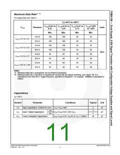
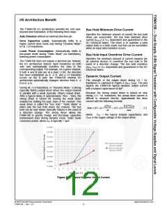
Dynamic Output Current
The strength of the output driver during LH / HL
transitions is captured in Figure 3 (IOLH, IOHD). The plot
depicts the FXMA108 typical dynamic output current
with a lumped capacitance of 4pF.
During HL / LH transitions, or “Dynamic Mode,” a strong
(typically 30mA) output driver drives the output channel
in parallel with a weak (typically 100µA) output driver.
After a typical delay of approximately 10ns – 50ns, the
strong driver is turned off, leaving the weak driver
enabled for holding the logic state of the channel. This
weak driver is called the “bus hold.” “Static Mode” is
when only the bus hold drives the channel. The bus
hold can be over ridden (typically 500µA) in the event of
a direction change. The strong driver allows the
FXMA108 to quickly charge and discharge capacitive
transmission lines during dynamic mode. Static mode
conserves power, where ICC is typically < 5µA.
Because the strong output driver is turned on only
during LH / HL transitions, the actual drive current is
difficult to measure directly. Approximate the drive
current with the following formula:
ΔVOUT
Δt
0.6*VCCO
IOHD ≈ (CI / O)×
= (CI / O)×
(1)
tRISE
where
CI/O = the typical lumped capacitance and
VCCO is the supply voltage of the output driver.
Figure 3.
Typical Dynamic Output Current
© 2010 Fairchild Semiconductor Corporation
FXMA108 • Rev. 1.0.1
www.fairchildsemi.com
12

 FAIRCHILD [ FAIRCHILD SEMICONDUCTOR ]