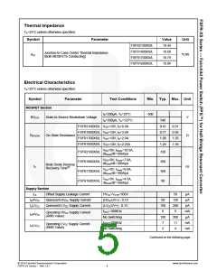
Thermal Impedance
TA=25°C unless otherwise specified.
Symbol
Parameter
Value
10.44
10.68
10.79
10.89
Unit
FSFR2100XS/L
FSFR1800XS/L
FSFR1700XS/L
FSFR1600XS/L
Junction-to-Case Center Thermal Impedance
(Both MOSFETs Conducting)
θJC
ºC/W
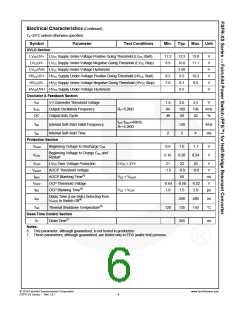
Electrical Characteristics
TA=25°C unless otherwise specified.
Symbol
Parameter
Test Conditions
Min. Typ. Max. Unit
MOSFET Section
500
ID=200μA, TA=25°C
ID=200μA, TA=125°C
BVDSS
Drain-to-Source Breakdown Voltage
V
540
FSFR2100XS/L VGS=10V, ID=6.0A
0.41
0.77
1.00
1.25
0.51
0.95
1.25
1.55
FSFR1800XS/L
FSFR1700XS/L
FSFR1600XS/L
VGS=10V, ID=3.0A
VGS=10V, ID=2.0A
VGS=10V, ID=2.25A
RDS(ON)
On-State Resistance
Ω
VGS=0V, IDiode=10.5A,
dIDiode/dt=100A/μs
FSFR2100XS/L
FSFR1800XS/L
FSFR1700XS/L
FSFR1600XS/L
120
160
160
90
VGS=0V, IDiode=7.0A,
dIDiode/dt=100A/μs
Body Diode Reverse
Recovery Time(6)
trr
ns
VGS=0V, IDiode=6.0A,
dIDiode/dt=100A/μs
VGS=0V, IDiode=4.5A,
dIDiode/dt=100A/μs
Supply Section
ILK
Offset Supply Leakage Current
Quiescent HVCC Supply Current
HVCC=VCTR=500V
(HVCCUV+) - 0.1V
(LVCCUV+) - 0.1V
fOSC=100KHz
50
120
200
9
μA
μA
IQHVCC
IQLVCC
50
100
6
Quiescent LVCC Supply Current
μA
mA
μA
Operating HVCC Supply Current
(RMS Value)
IOHVCC
IOLVCC
No Switching
100
7
200
11
fOSC=100KHz
mA
mA
Operating LVCC Supply Current
(RMS Value)
No Switching
2
4
Continued on the following page…
© 2010 Fairchild Semiconductor Corporation
FSFR-XS Series • Rev.1.0.1
www.fairchildsemi.com
5

 FAIRCHILD [ FAIRCHILD SEMICONDUCTOR ]