Integrated Power Functions
•
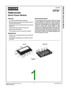
600V-10A IGBT inverter for three-phase DC/AC power conversion (Please refer to Figure 3)
Integrated Drive, Protection and System Control Functions
•
For inverter high-side IGBTs: Gate drive circuit, High voltage isolated high-speed level shifting
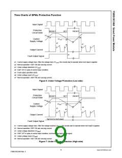
Control circuit under-voltage (UV) protection
Note) Available bootstrap circuit example is given in Figures 10 and 11.
•
For inverter low-side IGBTs: Gate drive circuit, Short circuit protection (SC)
Control supply circuit under-voltage (UV) protection
•
•
Fault signaling: Corresponding to a UV fault (Low-side supply)
Input interface: 3.3/5V CMOS/LSTTL compatible, Schmitt trigger input
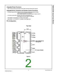
Pin Configuration
Top View
13.3
(1) VCC(L)
(2) COM
(3) IN(UL)
(4) IN(VL)
(5) IN(WL)
(6) VFO
(21) NU
(22) NV
(23) NW
19.1
(7) CFOD
(8) CSC
(9) IN(UH)
(24) U
Case Temperature (T )
C
(10) VCC(UH)
(11) VB(U)
(12) VS(U)
(13) IN(VH)
(14) VCC(VH)
(15) VB(V)
(16) VS(V)
(17) IN(WH)
(18) VCC(WH)
(19) VB(W)
Detecting Point
(25) V
(26) W
(27) P
Ceramic Substrate
(20) VS(W)
Figure 2.
2
www.fairchildsemi.com
FSBS10CH60 Rev. C

 FAIRCHILD [ FAIRCHILD SEMICONDUCTOR ]