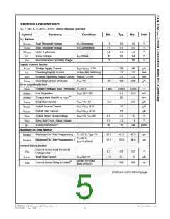
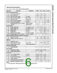
Electrical Characteristics
VCC = 14V, TA = -40°C~+125°C, unless otherwise specified.
Symbol
Parameter
Conditions
Min.
Typ.
Max.
Units
VCC Section
VSTART
VSTOP
Start Threshold Voltage
Stop Threshold Voltage
UVLO Hysteresis
VCC Increasing
VCC Decreasing
11
7.5
3.0
20
12
8.5
3.5
22
13
9.5
4.0
24
V
V
V
V
V
HYUVLO
VZ
Zener Voltage
ICC=20mA
VOP
Recommended Operating Range
13
20
Supply Current Section
ISTART Startup Supply Current
IOP Operating Supply Current
VCC=VSTART-0.2V
120
1.5
2.5
160
190
3.0
µA
mA
mA
µA
Output Not Switching
IDOP
Dynamic Operating Supply Current 50kHZ, CI=1nF
Operating Current at Disable VINV=0V
4.0
230
IOPDIS
90
Error Amplifier Section
VREF1
ΔVREF1
ΔVREF2
IEA,BS
Voltage Feedback Input Threshold1 TA=25°C
2.465
2.500
0.1
2.535
10.0
V
Line Regulation
VCC=14V~20V
mV
mV
µA
(4)
Temperature Stability of VREF1
Input Bias Current
20
VINV=1V~4V
-0.5
0.5
IEAS,SR
Output Source Current
VINV=VREF -0.1V
VINV=VREF +0.1V
VINV=1V, VCS=0V
-12
12
µA
µA
IEAS,SK
VEAH
VEAZ
gm
Output Sink Current
Output Upper Clamp Voltage
6.0
0.9
90
6.5
1.0
115
7.0
1.1
140
V
Zero-Duty Cycle Output Voltage
Transconductance(4)
V
µmho
Maximum On-Time Section
tON,MAX1
tON,MAX2
Maximum On-Time Programming 1 TA=25°C, VZCD=1V
35.5
11.2
41.5
13.0
47.5
14.8
µs
µs
TA=25°C,
Maximum On-Time Programming 2
IZCD=0.469mA
Current-Sense Section
Current-Sense Input Threshold
Voltage Limit
VCS
ICS,BS
tCS,D
0.7
0.8
-0.1
350
0.9
1.0
500
V
Input Bias Current
VCS=0V~1V
-1.0
µA
ns
dV/dt=1V/100ns,
from 0V to 5V
Current-Sense Delay to Output(4)
Continued on the following page…
© 2010 Fairchild Semiconductor Corporation
FAN7930C • Rev. 1.0.0
www.fairchildsemi.com
5

 FAIRCHILD [ FAIRCHILD SEMICONDUCTOR ]