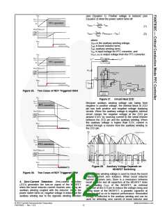
(see Equation 1). Positive voltage is induced (see
Equation 2) when the power switch turns off.
T
AUX
V
= −
⋅ V
AC
AUX
AUX
(1)
(2)
T
IND
T
AUX
V
=
⋅
(V
− V
AC
)
PFCOUT
T
IND
where:
VAUX is the auxiliary winding voltage;
TIND is boost inductor turns;
TIND auxiliary winding turns;
VAC is input voltage for PFC converter; and
VOUT_PFC is output voltage from the PFC converter.
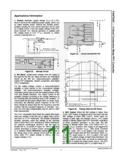
Figure 25. Two Cases of RDY Triggered HIGH
Figure 27. Circuit Near ZCD
Because auxiliary winding voltage can swing from
negative to positive voltage, the internal block in ZCD
pin has both positive and negative voltage clamping
circuits. When the auxiliary voltage is negative, internal
circuit clamps the negative voltage at the ZCD pin
around 0.65V by sourcing current to the serial resistor
between the ZCD pin and the auxiliary winding. When
the auxiliary voltage is higher than 6.5V, current is
sinked through a resistor from the auxiliary winding to
the ZCD pin.
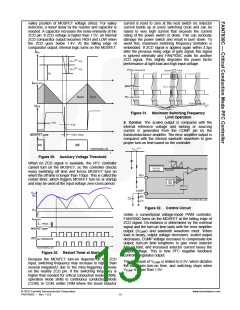
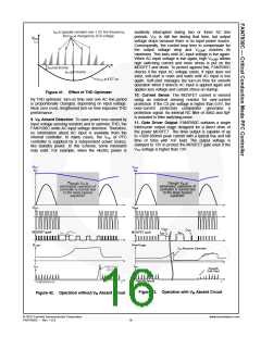
Figure 28. Auxiliary Voltage Depends on
MOSFET Switching
Figure 26. Two Cases of RDY Triggered LOW
The auxiliary winding voltage is used to check the boost
inductor current zero instance. When boost inductor
current becomes zero, there is a resonance between
boost inductor and all capacitors at the MOSFET drain
pin: including COSS of the MOSFET; an external
capacitor at the D-S pin to reduce the voltage rising and
falling slope of the MOSFET; a parasitic capacitor at
inductor; and so on to improve performance. Resonated
voltage is reflected to the auxiliary winding and can be
used for detecting zero current of boost inductor and
4. Zero-Current Detection: Zero-current detection
(ZCD) generates the turn-on signal of the MOSFET
when the boost inductor current reaches zero using an
auxiliary winding coupled with the inductor. When the
power switch turns on, negative voltage is induced at the
auxiliary winding due to the opposite winding direction
© 2010 Fairchild Semiconductor Corporation
FAN7930C • Rev. 1.0.0
www.fairchildsemi.com
12

 FAIRCHILD [ FAIRCHILD SEMICONDUCTOR ]