ST16C580
Table 7, SOFTWARE FLOW CONTROL FUNCTIONS
Cont-3 Cont-2 Cont-1 Cont-0 TX, RX software flow controls
0
1
0
1
X
X
X
1
0
0
1
1
X
X
X
0
X
X
X
X
0
1
0
1
X
X
X
X
0
0
1
1
No transmit flow control
Transmit Xon1/Xoff1
Transmit Xon2/Xoff2
Transmit Xon1 and Xon2/Xoff1 and Xoff2
No receive flow control
Receiver compares Xon1/Xoff1
Receiver compares Xon2/Xoff2
Transmit Xon1/ Xoff1.
Receiver compares Xon1 and Xon2,
Xoff1 and Xoff2
0
1
0
1
1
0
1
1
1
1
1
1
Transmit Xon2/Xoff2
Receiver compares Xon1 and Xon2/Xoff1 and Xoff2
Transmit Xon1 and Xon2/Xoff1 and Xoff2
Receiver compares Xon1 and Xon2/Xoff1 and Xoff2
No transmit flow control
Receiver compares Xon1 and Xon2/Xoff1 and Xoff2
EFR BIT-4:
EFR BIT-5:
Enhanced function control bit. The content of the IER
bits 4-7, ISR bits 4-5, FCR bits 4-5, and MCR bits 5-7
can be modified and latched. After modifying any bits
in the enhanced registers, EFR bit-4 can be set to a
logic 0 to latch the new values. This feature prevents
existing software from altering or overwriting the 580
enhanced functions.
Logic 0 = Special Character Detect Disabled (normal
default condition)
Logic 1 = Special Character Detect Enabled. The 580
compares each incoming receive character with Xoff-
2 data. If a match exists, the received data will be
transferred to FIFO and ISR bit-4 will be set to indicate
detection of special character. Bit-0 in the X-registers
correspondswiththeLSBbitforthereceivecharacter.
Whenthisfeatureisenabled, thenormalsoftwareflow
control must be disabled (EFR bits 0-3 must be set to
a logic 0).
Logic 0 = disable/latch enhanced features. IER bits 4-
7, ISR bits 4-5, FCR bits 4-5, and MCR bits 5-7 are
savedtoretaintheusersettings, thenIERbits4-7, ISR
bits 4-5, FCR bits 4-5, and MCR bits 5-7 are initialized
to the default values shown in the Internal Resister
Table. After a reset, the IER bits 4-7, ISR bits 4-5, FCR
bits 4-5, and MCR bits 5-7 are set to a logic 0 to be
compatible with ST16C550 mode. (normal default
condition).
Logic 1 = Enables the enhanced functions. When this
bit is set to a logic 1 all enhanced features of the 580
areenabledandusersettingsstoredduringaresetwill
be restored.
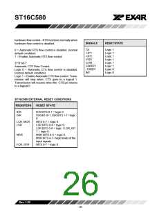
EFR BIT-6:
Automatic RTS may be used for hardware flow control
by enabling EFR bit-6. When AUTO RTS is selected,
an interrupt will be generated when the receive FIFO
is filled to the programmed trigger level and -RTS will
go to a logic 1 at the next trigger level. -RTS will return
toalogic0whendataisunloadedbelowthenextlower
trigger level (Programmed trigger level -1). The state
of this register bit changes with the status of the
Rev.1.20
25

 EXAR [ EXAR CORPORATION ]