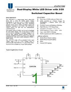
EUP2796
Soft-Start
This inrush current results in a current and voltage
spike at the input of the part. By only applying the
PWM signal to ENM/ENS, the charge pump stays on
continuously and much lower input noise results.
In cases where a PWM signal must be connected to
the EN pin, measures can be taken to reduce the
magnitude of the charge-pump turn-on voltage spikes.
More input capacitance, series resistors and/or ferrite
beads may provide benefits.
The EUP2796 contains internal soft-start circuitry to
limit input inrush currents when the part is enabled.
Soft start is implemented internally with
a
controlled turn-on of the internal voltage reference.
During soft start, the current through the LED outputs
rise at the rate of the reference voltage ramp. Due to
the soft-start circuitry, turn-on time of the EUP2796 is
approximately 100µs (typ.).
Thermal Protection
Capacitor Selection
Internal thermal protection circuitry disables the
EUP2796 when the junction temperature exceeds
160˚C (typ.). This feature protects the device from
being damaged by high die temperatures that might
otherwise result from excessive power dissipation.
The device will recover and operate normally when
the junction temperature falls below 140˚C (typ.).It is
important that the board layout provides good thermal
conduction. This will help to keep the junction
temperature within specified operating ratings.
The EUP2796 requires 4 external capacitors for
proper operation. Surface-mount multi-layer ceramic
capacitors are recommended. These capacitors are
small, inexpensive and have very low equivalent
series resistance (ESR<20mΩ typ.). Tantalum
capacitors, OS-CON capacitors, and aluminum
electrolytic capacitors are not recommended for use
with the EUP2796 due to their high ESR, as
compared to ceramic capacitors.
For most applications, ceramic capacitors with X7R
or X5R temperature characteristic are preferred for
use with the EUP2796. These capacitors have tight
capacitance tolerance (as good as ±10%) and hold
their value over temperature (X7R: ±15% over -55˚C
to 125˚C; X5R: ±15% over -55˚C to 85˚C).
Adjusting LED Brightness (PWM control)
Perceived LED brightness can be adjusted using a
PWM control signal to turn the EUP2796 current
sources ON and OFF at a rate faster than perceptible
by the eye. When this is done, the total brightness
perceived is proportional to the duty cycle (D) of the
PWM signal (D = the percentage of time that the LED
is on in every PWM cycle). A simple example: if the
LEDs are driven at 15mA each with a PWM signal
that has a 50% duty cycle, perceived LED brightness
will be about half as bright as compared to when the
LEDs are driven continuously with 15mA. A PWM
signal thus provides brightness (dimming) control for
the solution.
Capacitors
with
Y5V
or
Z5Utemperature
characteristic are generally not recommended for
use with the EUP2796. Capacitors with these
temperature characteristics typically have wide
capacitance tolerance (80%,-20%) and vary
significantly over temperature (Y5V: 22%, -82% over
-30˚C to 85˚C range; Z5U: 22%, -56% over 10˚C to
85˚C range). Under some conditions, a nominal 1µF
Y5V or Z5U capacitor could have a capacitance of
only 0.1µF. Such detrimental deviation is likely to
cause Y5V and Z5U capacitors to fail to meet the
minimum capacitance requirements of the EUP2796.
For LED driver applications, the input voltage ripple
is more important than output ripple. Input ripple is
controlled by input capacitor CIN, increasing the
value of input capacitance can further reduce the
ripple. Practically, the input voltage ripple depends on
the power supply’s impedance. If a single input
capacitor CIN cannot satisfy the requirement of
application, it is necessary to add a low-pass filter.
The minimum recommended PWM frequency is
100Hz. Frequencies below this may be visibly
noticeable as flicker or blinking. The maximum
recommended PWM frequency is 1kHz. Frequencies
above this may cause interference with internal
current driver circuitry.
The preferred method for applying a PWM signal to
adjust brightness is to keep the master EN voltage ON
continuously and to apply the PWM signal(s) to the
current source enable pin(s): ENM and/or ENS. The
benefit of this type of connection can be best
understood with a contrary example. When a PWM
signal is connected to the master enable (EN) pin, the
charge pump repeatedly turns on and off. Every time
the charge pump turns on, there is an inrush of
current as capacitances, both internal and external, are
recharged.
DS2796 Ver1.0 Feb. 2007
8

 EUTECH [ EUTECH MICROELECTRONICS INC ]