EUP2796
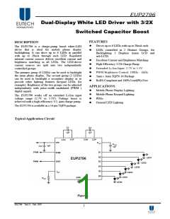
Application Information
Enable Pins: ENM, ENS
Maximum Output Current, Maximum LED
The EUP2796 has 2 enable pins-ENM and ENS,
which control the main and sub LEDs. All two are
active-high logic (HIGH = ON). When both of ENM
or ENS voltage is low (<0.5V), the part is in
shutdown mode. All internal circuitry is OFF and the
part consumes almost no supply current when the
EUP2796 is shutdown. When the voltage on either of
ENM and ENS pin is high (>1.1V), the part is active.
The charge pump is ON, and turn on the output
currents to drive the LEDs. ENM activates
/deactivates the four group-A outputs (D1-D4). ENS
activates/deactivates the two group-B outputs
(D5-D6).
Voltage, Minimum Input Voltage
The EUP2796 can drive 6 LEDs at 15mA each from
an input voltage as low as 3.0V, so long as the LEDs
have a forward voltage of 3.6V or less (room
temperature).
The statement above is a simple example of the LED
drive capabilities of the EUP2796. The statement
contains the key application parameters that are
required to validate an LED- drive design using the
EUP2796: LED current (ILED), number of active
LEDs (N), LED forward voltage (VLED), and mini-
mum input voltage (VIN-MIN).
The equation below can be used to estimate the total
output current capability of the EUP2796:
There is no pull down resistors that are connected
internally between each of the enable pins to ground.
1.5∗V − V
Setting LED Currents
IN
LED
I
I
=
=
, eq.1
( )
LED _ MAX
LED _ MAX
The output currents of the EUP2796 can be set to a
desired value simply by connecting an appropriately
sized resistor (RSET) between the ISET pin of the
EUP2796 and GND. The output currents (LED
currents) are proportional to the current that flows out
of the ISET pin. The output currents are a factor of 100
greater than the ISET current. The feedback loop of an
internal amplifier sets the voltage of the ISET pin to
1.18V(typ.). Placing a resistor between ISET and GND
programs the ISET current, and thus the LED currents.
The statements above are simplified in the equations
below:
N ∗R
+ K
OUT HR
1.5∗V − V
IN
LED
ROUT – Output resistance. This parameter models the
internal losses of the charge pump that result in
voltage droop at the pump output POUT. Since the
magnitude of the voltage droop is proportional to the
total output current of the charge pump, the loss
parameter is modeled as a resistance. The output
resistance of the EUP2796 is typically 4Ω (VIN = 3.0V,
TA = 25˚C). In equation form:
I
= 100×
=100×
(
V
× R
)
SET
DXX
SET
V
= 1.5× V − N× I
× R
eq.2
( )
OUT
POUT
IN
LED
R
(
1.18V× I
)
DXX
SET
KHR – Headroom constant. This parameter models the
minimum voltage required to be present across the
current sources for them to regulate properly. This
minimum voltage is proportional to the programmed
LED current, so the constant has units of mV/mA.
The typical KHR of the EUP2796 is 12mV/mA. In
equation form:
V
− V
)
> K
× I
eq.3
( )
LED
POUT
LED
HR
The "ILED-MAX" equation (eq. 1) is obtained from
combining the ROUT equation (eq. 2) with the KHR
equation (eq. 3) and solving for ILED. Maximum LED
current is highly dependent on minimum input
voltage and LED forward voltage. Output current
capability can be increased by raising the minimum
input voltage of the application, or by selecting an
LED with a lower forward voltage. Excessive power
dissipation may also limit output current capability of
an application.
DS2796 Ver1.0 Feb. 2007
7

 EUTECH [ EUTECH MICROELECTRONICS INC ]