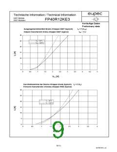
Technische Information / Technical Information
IGBT-Module
IGBT-Modules
FP40R12KE3
Vorläufige Daten
Preliminary data
Elektrische Eigenschaften / Electrical properties
Charakteristische Werte / Characteristic values
min. typ. max.
Modulinduktivität
stray inductance module
Ls CE
-
-
100
nH
Modul Leitungswiderstand, Anschlüsse-Chip
TC = 25°C
RCC'+EE'
-
7
-
mW
lead resistance, terminals-chip
min. typ. max.
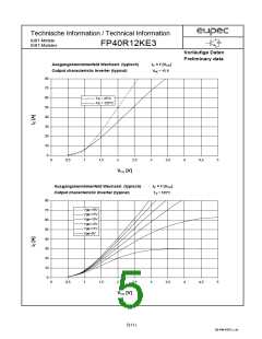
Diode Wechselrichter/ Diode Inverter
VGE = 0V, Tvj = 25°C,
VGE = 0V, Tvj = 125°C,
IF =
IF =
VF
IRM
Qr
40 A
-
-
1,75
1,75
2,3
-
V
V
Durchlaßspannung
forward voltage
40 A
IF=INenn
,
- diF/dt =
1000 A/µs
600 V
Rückstromspitze
peak reverse recovery current
VGE = -10V, Tvj = 25°C, VR
VGE = -10V, Tvj = 125°C, VR
=
=
-
-
45
46
-
-
A
A
600 V
IF=INenn
,
- diF/dt =
1000 A/µs
600 V
Sperrverzögerungsladung
recovered charge
VGE = -10V, Tvj = 25°C, VR
VGE = -10V, Tvj = 125°C, VR
=
=
-
-
4,4
8,4
-
-
µAs
µAs
600 V
IF=INenn
,
- diF/dt =
1000 A/µs
600 V
Abschaltenergie pro Puls
reverse recovery energy
VGE = -10V, Tvj = 25°C, VR
VGE = -10V, Tvj = 125°C, VR
=
=
ERQ
-
-
1,55
3,1
-
-
mWs
mWs
600 V
min. typ. max.
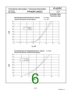
Transistor Brems-Chopper/ Transistor Brake-Chopper
VGE = 15V, Tvj = 25°C, IC =
VGE = 15V, Tvj = 125°C, IC =
VCE sat
15 A
15 A
-
-
1,7
2
2,2
-
V
V
Kollektor-Emitter Sättigungsspannung
collector-emitter saturation voltage
Gate-Schwellenspannung
gate threshold voltage
VCE = VGE
,
Tvj = 25°C, IC =
VGE(TO)
Cies
0,5 mA
5,0
5,8
1,1
5,0
-
6,5
V
f = 1MHz, Tvj = 25°C
VCE = 25 V, VGE = 0 V
Eingangskapazität
input capacitance
-
-
-
-
-
nF
mA
nA
Kollektor-Emitter Reststrom
collector-emitter cut off current
VGE = 0V, Tvj = 25°C, VCE
=
ICES
1200 V
Gate-Emitter Reststrom
gate-emitter leakage current
VCE = 0V, VGE = 20V, Tvj = 25°C
IGES
400
siehe Wechselrichter in Dbl FP15R12KE3
see inverter in datasheet FP15R12KE3
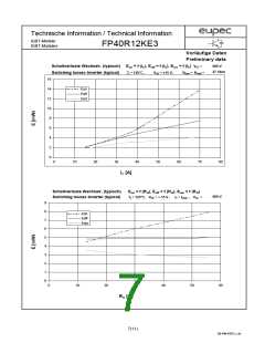
Schaltverluste und -bedingungen
Switching losses and conditions
min. typ. max.
Diode Brems-Chopper/ Diode Brake-Chopper
Tvj = 25°C,
Tvj = 125°C,
IF =
IF =
VF
15 A
15 A
-
-
2,05
2,2
2,5
-
V
V
Durchlaßspannung
forward voltage
siehe Wechselrichter in Dbl FB10R12KE3
see inverter in datasheet FB10R12KE3
Schaltverluste und -bedingungen
Switching losses and conditions
min. typ. max.
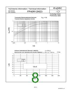
NTC-Widerstand/ NTC-Thermistor
Nennwiderstand
rated resistance
TC = 25°C
R25
-
5
-
kW
%
Abweichung von R100
deviation of R100
TC = 100°C, R100 = 493 W
TC = 25°C
-5
5
DR/R
P25
Verlustleistung
power dissipation
20
mW
K
B-Wert
B-value
R2 = R1 exp [B(1/T2 - 1/T1)]
B25/50
3375
3(11)
DB-PIM-IGBT3_1.xls

 EUPEC [ EUPEC GMBH ]