J2000 SERIES/J2100
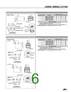
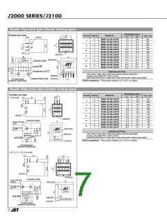
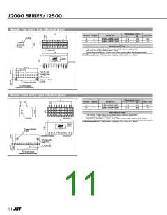
Header Top entry type (Center locking type)
Dimensions (mm)
A
2.5
Double-row type
Circuits Keying
Model No.
Q’ty / box
A
B
3.4
Line No.
X
B06B-J21DK-GGXR
B06B-J21DK-GGYR
B08B-J21DK-GGXR
B08B-J21DK-GGYR
B10B-J21DK-GGXR
B10B-J21DK-GGYR
B12B-J21DK-GGXR
B12B-J21DK-GGYR
B16B-J21DK-GGXR
B16B-J21DK-GGYR
B20B-J21DK-GGXR
B20B-J21DK-GGYR
5.0
10.2
10.2
12.7
12.7
15.2
15.2
17.7
17.7
22.7
22.7
27.7
27.7
252
252
204
204
168
168
144
144
108
108
84
6
Y
5.0
X
7.5
8
Y
7.5
X
10.0
10.0
12.5
12.5
17.5
17.5
22.5
22.5
X
10
Y
3.22
Keying No.
X
12
(B)
B
Y
±0.05
A
Series name
X
Connector outline
±0.05
16
2.5
Y
X
+0.05
–0.03
N-φ0.85
20
J-2100
Y
84
X
5
±0.05
Through-hole 2-φ2
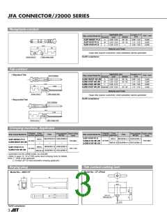
Material and Finish
4
3
2 1
Tab contact: Copper alloy, nickel-undercoated, selective gold-plated
Housing: Glass-filled PBT, UL94V-0, black
Reinforcing metal fixture: Copper alloy, nickel-undercoated, selective gold-plated
Keying No.
Circuit No.
Copper foil land 2-(φ3)
PC board layout
2.5
RoHS compliance This product displays (LF) (AU) on a label.
(viewed from component side)
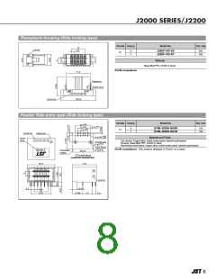
Header Side entry type (Center locking type)
Dimensions (mm)
Double-row type
Circuits Keying
Model No.
Q’ty / box
A
2.5
A
B
2.5
(7)
• 6 circuits
X
S06B-J21DK-GGXR
S06B-J21DK-GGYR
S08B-J21DK-GGXR
S08B-J21DK-GGYR
S10B-J21DK-GGXR
S10B-J21DK-GGYR
S12B-J21DK-GGXR
S12B-J21DK-GGYR
S16B-J21DK-GGXR
S16B-J21DK-GGYR
S20B-J21DK-GGXR
S20B-J21DK-GGYR
5.0
10.2
10.2
12.7
12.7
15.2
15.2
17.7
17.7
22.7
22.7
27.7
27.7
252
252
204
204
168
168
144
144
108
108
84
6
Y
5.0
7.5
X
8
A
B
Y
7.5
X
10.0
10.0
12.5
12.5
17.5
17.5
22.5
22.5
10
Y
X
Line No.
X
12
Y
Keying No.
X
Connector outline
16
B
Copper foil land
Y
(φ3.4)
X
20
Y
84
Through-hole
Series name
Keying No.
±0.05
φ2
Material and Finish
Tab contact: Copper alloy, nickel-undercoated, selective gold-plated
Housing: Glass-filled PBT, UL94V-0, black
J-2100
±0.05
+0.05
X
2.5
φ0.85
Reinforcing metal fixture: Copper alloy, nickel-undercoated, selective gold-plated
–0.03
±0.05
5
3
2 1
RoHS compliance This product displays (LF) (AU) on a label.
Circuit No.
(B
)
PC board layout
(viewed from component side)
• 8, 10, 12, 16, 20 circuits
A
2.5
(7)
2.5
A
B
Line No.
X
Keying No.
Connector outline
Copper foil land
B
Series name
2-(φ3.4)
Through-hole
±0.05
2-φ2
J-2100
±0.05
+0.05
2.5
φ0.85
–0.03
X
Keying No.
Circuit No.
±0.05
A
5
4 3 2 1
(B)
PC board layout
(viewed from component side)
7

 ETC [ ETC ]