Document No.: FT_000288
FT232H SINGLE CHANNEL HI-SPEED USB TO MULTIPURPOSE UART/FIFO IC
Datasheet Version 1.8
Clearance No.: FTDI #199
List of Figures
Figure 2.1 FT232H Block Diagram...................................................................................................4
Figure 3.1 FT232H Schematic Symbol .............................................................................................7
Figure 4.1 RS232 Configuration.................................................................................................... 24
Figure 4.2 Dual RS422 Configuration............................................................................................. 25
Figure 4.3 Dual RS485 Configuration............................................................................................. 26
Figure 4.4 FT245 Synchronous FIFO Interface Signal Waveforms...................................................... 27
Figure 4.5 FT245 Asynchronous FIFO Interface READ Signal Waveforms............................................ 29
Figure 4.6 FT245 Asynchronous FIFO Interface WRITE Signal Waveforms .......................................... 29
Figure 4.7 FT1248 Bus with Single Master and Slave....................................................................... 30
Figure 4.8: FT1248 Basic Waveform Protocol.................................................................................. 30
Figure 4.9: FT1248 Command Structure........................................................................................ 31
Figure 4.10: FT1248 1-bit Mode Protocol (WRITE) .......................................................................... 32
Figure 4.11: FT1248 1-bit Mode Protocol (READ)............................................................................ 32
Figure 4.12 Synchronous Bit-Bang Mode Timing Interface Example................................................... 35
Figure 4.13 Bit-bang Mode Dataflow Illustration Diagram................................................................. 35
Figure 4.14 MPSSE Signal Waveforms ........................................................................................... 36
Figure 4.15 Adaptive Clocking Interconnect.................................................................................... 37
Figure 4.16: Adaptive Clocking waveform. ..................................................................................... 37
Figure 4.17 Fast Serial Interface Signal Waveforms......................................................................... 38
Figure 4.18 Fast Serial Interface Output Data................................................................................. 39
Figure 4.19 Fast Serial Interface Input Data................................................................................... 39
Figure 4.20 Fast Serial Interface Example...................................................................................... 40
Figure 4.21 CPU-Style FIFO Interface Operation Signal Waveforms................................................... 41
Figure 4.22 CPU-Style FIFO Interface Example ............................................................................... 42
Figure 4.23 Dual LED UART Configuration...................................................................................... 43
Figure 4.24 Single LED UART Configuration.................................................................................... 43
Figure 4.25: Using SIWU#........................................................................................................... 44
Figure 6.1 Bus Powered Configuration Example 1............................................................................ 51
Figure 6.2 Self Powered Configuration Example 1 ........................................................................... 52
Figure 6.3 Self Powered Configuration Example 2 ................................................................... 53
Figure 6.4 Recommended FT232H Oscillator Configuration............................................................... 54
Figure 7.1 EEPROM Interface........................................................................................................ 55
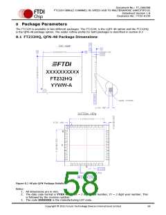
Figure 8.1 48 pin QFN Package Details .......................................................................................... 58
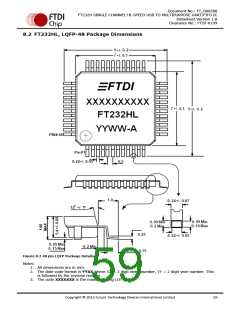
Figure 8.2 48 pin LQFP Package Details ......................................................................................... 59
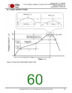
Figure 8.3 48 pin LQFP and QFN Reflow Solder Profile ..................................................................... 60
Copyright © 2012 Future Technology Devices International Limited
64

 ETC [ ETC ]