Document No.: FT_000288
FT232H SINGLE CHANNEL HI-SPEED USB TO MULTIPURPOSE UART/FIFO IC
Datasheet Version 1.8
Clearance No.: FTDI #199
3.5 Pin Configurations
The following section describes the function of the pins when the device is configured in different modes
of operation.
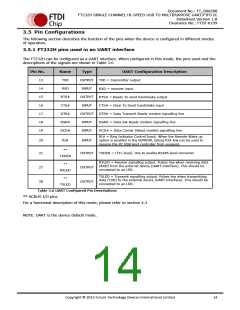
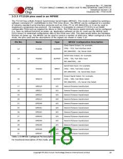
3.5.1 FT232H pins used in an UART interface
The FT232H can be configured as a UART interface. When configured in this mode, the pins used and the
descriptions of the signals are shown in Table 3.6
Pin No.
13
Name
TXD
Type
OUTPUT
INPUT
UART Configuration Description
TXD = transmitter output
14
RXD
RXD = receiver input
15
RTS#
CTS#
DTR#
DSR#
DCD#
OUTPUT
INPUT
RTS# = Ready To send handshake output
CTS# = Clear To Send handshake input
DTR# = Data Transmit Ready modem signalling line
DSR# = Data Set Ready modem signalling line
DCD# = Data Carrier Detect modem signalling line
16
17
OUTPUT
INPUT
18
19
INPUT
RI# = Ring Indicator Control Input. When the Remote Wake up
option is enabled in the EEPROM, taking RI# low can be used to
resume the PC USB Host controller from suspend.
20
21
RI#
INPUT
**
OUTPUT
TXDEN = (TTL level). Use to enable RS485 level converter
TXDEN
RXLED = Receive signalling output. Pulses low when receiving data
(RXD) from the external device (UART Interface). This should be
connected to an LED.
**
27
28
OUTPUT
OUTPUT
RXLED
TXLED = Transmit signalling output. Pulses low when transmitting
data (TXD) to the external device (UART Interface). This should be
connected to an LED.
**
TXLED
Table 3.6 UART Configured Pin Descriptions
** ACBUS I/O pins
For a functional description of this mode, please refer to section 4.3
NOTE: UART is the device default mode.
Copyright © 2012 Future Technology Devices International Limited
14

 ETC [ ETC ]