ZSPM1025A
True Digital PWM Controller (Single-Phase, Single-Rail)
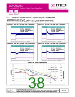
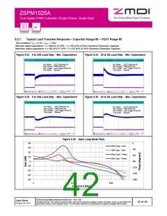
5.2.7.
Typical Load Transient Response – Capacitor Range #3 – VOUT Range #2
Test conditions: VIN = 12.0V, VOUT = 1.80V
Minimum output capacitance: 1 x 100µF/6.3V X5R + 2 x 470 µF/6.3V/7mΩ Aluminum Electrolytic Capacitor
Maximum output capacitance: 6 x 100 µF/6.3V X5R + 5 x 470 µF/6.3V/7mΩ Aluminum Electrolytic Capacitor
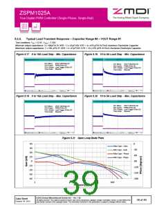
Figure 5.32 5 to 20A Load Step – Min. Capacitance
Figure 5.33 20 to 5A Load Step – Min. Capacitance
Ch1 (Blue): VOUT 50mV/div AC
Ch2 (LCyan): PWM 5V/div DC
Ch3: (Violet): Load Trigger 5V/div DC
Time Scale: 20µs/div
Ch1 (Blue): VOUT 50mV/div AC
Ch2 (LCyan): PWM 5V/div DC
Ch3: (Violet): Load Trigger 5V/div DC
Time Scale: 20µs/div
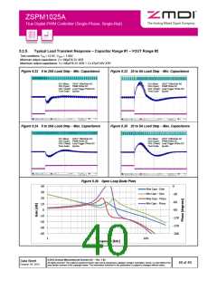
Figure 5.34 5 to 20A Load Step – Max. Capacitance
Figure 5.35 20 to 5A Load Step – Max. Capacitance
Ch1 (Blue): VOUT 50mV/div AC
Ch2 (LCyan): PWM 5V/div DC
Ch3: (Violet): Load Trigger 5V/div DC
Time Scale: 20µs/div
Ch1 (Blue): VOUT 50mV/div AC
Ch2 (LCyan): PWM 5V/div DC
Ch3: (Violet): Load Trigger 5V/div DC
Time Scale: 20µs/div
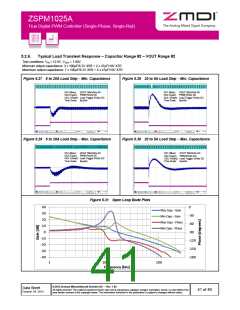
Figure 5.36 Open Loop Bode Plots
40
30
0
Max Caps - Gain
-30
Min Caps - Gain
20
Max Caps - Phase
-60
10
Min Caps - Phase
0
-90
-10
-20
-30
-40
-120
-150
-180
1
10
Frequency [kHz]
100
© 2013 Zentrum Mikroelektronik Dresden AG — Rev. 1.00
All rights reserved. The material contained herein may not be reproduced, adapted, merged, translated, stored, or used without the
prior written consent of the copyright owner. The information furnished in this publication is subject to changes without notice.
Data Sheet
October 24, 2013
42 of 46

 ETC [ ETC ]