Operation
Sleep support
n
n
SP (Cyclic Sleep Period)
DP (Disassociated Cyclic Sleep Period)
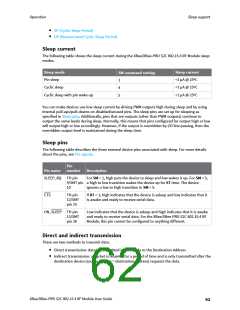
Sleep current
The following table shows the sleep current during the XBee/XBee-PRO S2C 802.15.4 RF Module sleep
modes.
Sleep mode
Sleep current
<1 µA @ 25ºC
<1 µA @ 25ºC
<1 µA @ 25ºC
SM command setting
Pin sleep
1
4
5
Cyclic sleep
Cyclic sleep with pin wake-up
You can make devices use low sleep current by driving PWM outputs high during sleep and by using
internal pull-ups/pull-downs on disabled/unused pins. The sleep pins are set up for sleeping as
specified in Sleep pins. Additionally, pins that are outputs (other than PWM outputs) continue to
output the same levels during sleep. Normally, this means that pins configured for output high or low
will output high or low accordingly. However, if the output is overridden by I/O line passing, then the
overridden output level is maintained during the sleep time.
Sleep pins
The following table describes the three external device pins associated with sleep. For more details
about the pins, see Pin signals.
Pin
number
Pin name
Description
SLEEP_RQ TH pin
For SM = 1, high puts the device to sleep and low wakes it up. For SM = 5,
9/SMT pin a high to low transition wakes the device up for ST time. The device
10
ignores a low to high transition in SM = 5.
CTS
TH pin
12/SMT
pin 25
If D7 = 1, high indicates that the device is asleep and low indicates that it
is awake and ready to receive serial data.
ON_SLEEP TH pin
13/SMT
Low indicates that the device is asleep and high indicates that it is awake
and ready to receive serial data. For the XBee/XBee-PRO S2C 802.15.4 RF
Module, this pin cannot be configured to anything different.
pin 26
Direct and indirect transmission
There are two methods to transmit data:
n
Direct transmission: data is transmitted immediately to the Destination Address
n
Indirect transmission: a packet is retained for a period of time and is only transmitted after the
destination device (source address = destination address) requests the data.
XBee/XBee-PRO S2C 802.15.4 RF Module User Guide
62

 ETC [ ETC ]