Migrate from XBee through-hole to surface-mount devices
Mount the devices
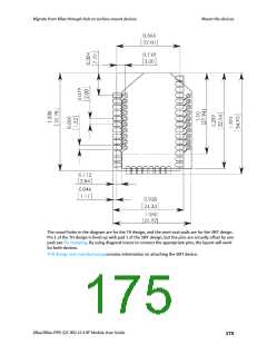
The round holes in the diagram are for the TH design, and the semi-oval pads are for the SMT design.
Pin 1 of the TH design is lined up with pad 1 of the SMT design, but the pins are actually offset by one
pad; see Pin mapping. By using diagonal traces to connect the appropriate pins, the layout will work
for both devices.
PCB design and manufacturing contains information on attaching the SMT device.
XBee/XBee-PRO S2C 802.15.4 RF Module User Guide
175

 ETC [ ETC ]