High Speed Backplane Connectors
Power Modules and Guide Hardware Reference (Continued)
Y
L
Housing
Contact
1
2
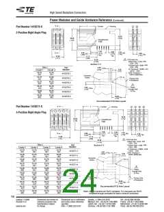
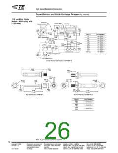
Part Number 1410279-X
2-Position Right Angle Plug
14.70
18.40
[.724]
[.579]
Daughtercard
Edge
5.50
[.217]
Ref.
2.00
[.079]
Typ.
3.50
[.138]
6.00
[.236]
Y
Ref.
3.60
[.142]
Ref.
Typ.
10.60
17.75
[.417]
[.699]
1
PCB Hole Dim.
33.38
± 0.02
Drilled Hole = 0.70
[1.314]
± .001
[.028
]
Section Y-Y
± 0.05
Finished Hole = 0.60
± .002
[.024
]
Dim. L
Part
Number
2.00
[.079]
5 Plcs.
Cu Thickness = 0.025 – 0.5
[.0010 – .020]
SnPb Thickness =
0.015 [.0006] Max.
5.50
[.217]
Circuit 1
Circuit 2
13.75
13.75
1410279-1
1410279-2
1410279-3
1410279-4
1410279-5
1410279-6
.541
.541
Connector
Outline
13.75
.541
12.25
.482
Pin 1a
Primary Side
of Backplane
13.75
.541
10.75
.423
1
10.75
. 423
10.75
.423
Plated
Through Hole
12 Plcs.
3.60
[.142]
3 Plcs.
12.25
.482
10.75
.423
12.25
.482
12.25
.482
18.00
[.709]
Ref.
Recommended PCB Hole Layout
L
Y
Part Number 1410271-X
Contact
Housing
1
2
3
4
4-Position Right Angle Plug
14.70
18.40
[.724]
[.579]
Daughtercard
Edge
5.50
[.217]
Ref.
2.00
[.079]
Typ.
3.50
[.138]
6.00
[.236]
Y
Ref.
3.60
[.142]
Ref.
Typ.
17.80
17.75
[.701]
[.699]
1
PCB Hole Dim.
33.38
[1.314]
± 0.02
Drilled Hole = 0.70
± .001
[.028
]
Dim. L
± 0.05
Part
SectionY-Y
Finished Hole = 0.60
± .002
Number
[.024
]
Cavity 1
Cavity 2
Cavity 3
Cavity 4
Cu Thickness = 0.025 – 0.50
[.0010 – .020]
13.75
.541
13.75
.541
13.75
13.75
.541
1410271-1
.541
2.00
[.079]
5 Plcs.
SnPb Thickness =
0.015 [.0006] Max.
5.50
[.217]
12.25
.482
13.75
.541
13.75
.541
12.25
.482
1410271-2
1410271-3
1410271-4
1410271-5
1410271-6
1410271-7
1410271-8
1410271-9
1-1410271-0
Connector
Outline
12.25
.482
13.75
.541
13.75
.541
10.75
.423
Pin 1a
10.75
. 423
13.75
.541
13.75
.541
10.75
.423
1
12.25
.482
13.75
.541
12.25
.482
10.75
.423
Plated
Through Hole
24 Plcs.
12.25
.482
12.25
.482
12.25
.482
12.25
.482
3.60
[.142]
10.75
. 423
12.25
.482
12.25
.482
10.75
.423
3 Plcs.
Primary Side
of Backplane
18.00
[.709]
10.75
. 423
10.75
. 423
10.75
. 423
10.75
.423
Ref.
Recommended PCB Hole Layout
10.75
. 423
13.75
.541
12.25
.482
10.75
.423
12.25
.482
10.75
. 423
10.75
.541
12.25
.482
Note: All part numbers are RoHS compliant. Tin-Lead parts are RoHS
compliant through exemption for lead in press-fit connectors.
160
Catalog 1773095
Revised 4-12
Dimensions are shown for
reference purposes only.
Specifications subject
to change.
Dimensions are in millimeters
and inches unless otherwise
specified.
Canada: +1 (905) 475-6222
UK: +44 (0) 800-267666
Mexico/C. Am.: +52 (0) 55-1106-0800
Latin/S. Am.: +54 (0) 11-4733-2200
Germany: +49 (0) 6251-133-1999
France: +33 (0) 1-3420-8686
Netherlands: +31 (0) 73-6246-999
China: +86 (0) 400-820-6015
www.te.com
USA: +1 (800) 522-6752

 ETC [ ETC ]