Page 50
Epson Research and Development
Vancouver Design Center
8.4 Writing Cursor/Ink Layer Images
This section describes how to write images to the Hardware Cursor and Ink Layer. The
Hardware Cursor is a 64x64 image at a color depth of 2 bpp. The Ink Layer is the same size
as the virtual display (width x height) at a color depth of 2 bpp. The Ink Layer may be
described as a non-moveable cursor with the same resolution as the display device.
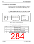
8.4.1 Hardware Cursor/Ink Layer Data Format
The Hardware Cursor/Ink Layer image is fixed at a color depth of 2 bpp. The following
diagram shows the Hardware Cursor/Ink Layer data format for a little endian system.
2 bpp:
bit 7
bit 0
P P P P
P P P P
3
4
0
1
2
7
5
6
A
A
B
B
A
A
B
B
A
A
B
B
A
A
B
B
0
4
0
1
1
2
2
3
3
7
Byte 0
4
5
5
6
6
7
Byte 1
P
= (A , B )
n n
n
Panel Display
Host Address
Hardware Cursor/Ink Layer Buffer
Figure 8-1: Hardware Cursor/Ink Layer Data Format
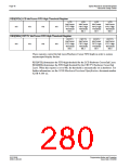
The image data for pixel n, (A ,B ), selects the color for pixel n as follows:
n
n
Table 8-6: Ink/Cursor Color Select
(An,Bn)
Color
Comments
Ink/Cursor Color 0 Register:
00
Color 0
For LCD, REG[076h], REG[077h], REG[078h].
For CRT/TV, REG[086h], REG[087h], REG[088h].
Ink/Cursor Color 1 Register:
01
Color 1
For LCD, REG[07Ah], REG[07Bh],REG[07Ch].
For CRT/TV, REG[08Ah], REG[08Bh], REG[08Ch].
10
11
Background
Ink/Cursor is transparent – show background
Inverted Background
Ink/Cursor is transparent – show inverted background
S1D13506
X25B-G-003-03
Programming Notes and Examples
Issue Date: 01/02/06

 EPSON [ EPSON COMPANY ]