Page 48
Epson Research and Development
Vancouver Design Center
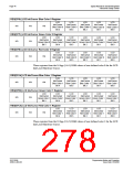
8.3.2 Examples
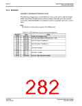
Example 5: Initializing the Hardware Cursor
The following example places an LCD Hardware Cursor at the end of a 2M byte display
buffer. SwivelView™ modes require software rotation of the Ink Layer. This can only
occur when a Dual Panel Buffer is not required. Color 0 is set to black, and color 1 is set to
white.
Note
The Hardware Cursor always requires 1024 (400h) bytes.
Table 8-3: LCD Hardware Cursor Initialization Sequence
Register
Value
Notes
Enable LCD hardware cursor
[070h]
[071h]
0000 0001
0000 0000
Set cursor start address to Memory Size - 1024
[072h]
[073h]
0000 0000
0000 0000
Set LCD Cursor X Position to 0
[074h]
[075h]
0000 0000
0000 0000
Set LCD Cursor Y Position to 0
Set Color 0 to black
[076h]
[077h]
[078h]
0000 0000
0000 0000
0000 0000
[07Ah]
[07Bh]
[07Ch]
0001 1111
0011 1111
0001 1111
Set Color 1 to white
[07Eh]
0000 0000
Set FIFO High Threshold to default
S1D13506
X25B-G-003-03
Programming Notes and Examples
Issue Date: 01/02/06

 EPSON [ EPSON COMPANY ]