Page 12
Epson Research and Development
Vancouver Design Center
2 Initialization
This section describes how to initialize the S1D13506. Sample code for performing initial-
ization of the S1D13506 is provided in the file init13506.c which is available on the
internet at www.eea.epson.com.
S1D13506 initialization can be broken into three steps.
• Enable the S1D13506 controller (if necessary identify the specific controller).
• Set all the registers to their initial values.
• Program the Look-Up Table (LUT) with color values. This section does not deal with
programming the LUT, for details see Section 4, “Look-Up Table (LUT)” .
The simplest way to generate initialization tables for the S1D13506 is to use the utility
program 13506CFG.EXE which to generates a header file that can be used by Windows CE
or the HAL. Otherwise modify the init13506.c file directly.
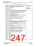
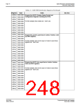
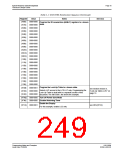
The following table represents the sequence and values written to the S1D13506 registers
to control a configuration with these specifications:
• 640x480 color format 1 dual passive LCD @ 78Hz.
• 16-bit data interface.
• 8 bit-per-pixel (bpp) color depth - 256 colors.
• 40 MHz input clock CLKI.
• CLKI used for BUSCLK (1:1); PCLK (2:1); MCLK (1:1).
• 50 ns EDO-DRAM, 2 CAS, 32 ms refresh.
Table 2-1: S1D13506 Initialization Sequenc e
Register
[001h]
Value
Notes
See Also
0000 0000 Enable the Memory/Register Select Bit.
0000 0000 Disable the display outputs.
[1FCh]
Setup GPIO as inputs; force low if outputs. The OEM may wish
GPIO for other purposes which our example does not
accommodate for.
[004h]
[008h]
0000 0000
0000 0000
Program the Clock Source selects.
In this case we have a single input clock source attached to the
CLKI pin. This example uses this as BUSCLK, as MCLK and
divide by 2 for PCLK. The CRT clock and MediaPlug clocks are
[010h]
[014h]
[018h]
[01Ch]
0000 0000
0001 0000
0000 0010 set to CLKI2 reducing power consumption (there is no CLKI2 in
this example). If either the CRT or MediaPlug is to be used an
input clock must be enabled before accessing the control
0000 0010
registers or LUT.
[01Eh]
0000 0001 Program CPU Wait States.
see REG[01Eh] for details
S1D13506
X25B-G-003-03
Programming Notes and Examples
Issue Date: 01/02/06

 EPSON [ EPSON COMPANY ]