Page 204
Epson Research and Development
Vancouver Design Center
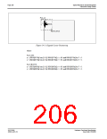
The Dual Panel Buffer is used for dual panel mode. Its memory requirement is:
Dual Panel Buffer (bytes)
=(W × H) / 4
for color mode
=(W × H) / 16
for monochrome mode
where W is the width of the panel in number of pixels, and H is the height of the panel in
number of lines.
The Dual Panel Buffer is always located at the end of the physical memory.
The Hardware Cursor or Ink Layer also takes up memory. If this memory is > 1KB, it must
be located at an 8KB boundary, otherwise it may be located at the last 1KB area. The
Hardware Cursor or Ink Layer must not overlap the image buffer or the Dual Panel Buffer.
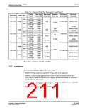
The following table summarizes the DRAM size requirement for 90° SwivelView™ for
different panel sizes and display modes. Note that DRAM size for the S1D13506 is limited
to either 512K byte or 2M byte. The calculation is based on the minimum required image
buffer size and the Dual Panel Buffer size. The Hardware Cursor/Ink Layer may or may not
fit within this minimum DRAM configuration – this is noted in the table. The hardware
cursor requires only 1KB of memory and so may resides at the last 1KB area if there is no
Dual Panel Buffer, otherwise it must reside at an 8KB boundary. The 2-bit ink layer
requires (W × H) / 4 bytes of memory; it must reside at an 8KB boundary. The table shows
only one possible Hardware Cursor/Ink Layer location – at the highest possible location
without interfering with the Dual Panel Buffer. It is also assumed that CRT/TV is not used.
S1D13506
X25B-A-001-10
Hardware Functional Specification
Issue Date: 01/02/06

 EPSON [ EPSON COMPANY ]