Page 202
Epson Research and Development
Vancouver Design Center
Note
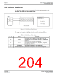
W is the width of the LCD panel in number of pixels, (or the height of the portrait win-
dow in number of lines).
H is the height of the panel in number of lines, (or the width of the portrait window in
number of pixels).
Note
The image must be written with a 1024 pixel offset between adjacent lines (1024 bytes
for 8 bpp mode or 2048 bytes for 15/16 bpp mode) and the display start address must be
calculated (see below).
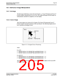
15.2.1 Register Programming
Enabling 90° Rotation on CPU Read/Write to Display Buffer
Set SwivelView™ Enable bit 0 to 1. All CPU accesses to the display buffer are translated
to provide 90° clockwise rotation of the display image. SwivelView™ Enable bit 1 should
be set to 0.
Memory Address Offset
The LCD Memory Address Offset register (REG[046h], REG[047h]) must be set for a
1024 pixel offset:
LCD Memory Address Offset (words)
= 1024
= 512
for 15/16 bpp mode
for 8 bpp mode
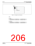
Display Start Address
As seen in Figure 15-1: “Relationship Between Screen Image and 90° Rotated Image in the
Display Buffer,” on page 201, the Display Start Address is determined by the location of
the image corner “C”, and it is generally non-zero. The LCD Display Start Address register
(REG[042h], REG[043h], REG[044h]) must be set accordingly.
LCD Display Start Address (words)
= (1024 - W)
= (1024 - W) / 2
for 15/16 bpp mode
for 8 bpp mode
where W is the width of the panel in number of pixels.
S1D13506
X25B-A-001-10
Hardware Functional Specification
Issue Date: 01/02/06

 EPSON [ EPSON COMPANY ]