Page 194
Epson Research and Development
Vancouver Design Center
13.5 TV Image Display and Positioning
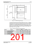
This section describes how to setup and position an image to be displayed on a TV. Figure
13-4: “NTSC/PAL Image Positioning,” on page 195 shows an image positioned on the TV
display with the related programmable parameters. The TV display area is shaded.
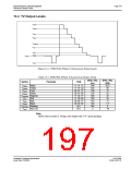
The size of the display image determines the register values for the Horizontal Display
Period, Horizontal Non-Display Period, Vertical Display Period, and Vertical Non-Display
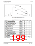
Period. The maximum and minimum values for these registers are given in Table 13-5:
“Minimum and Maximum Values for NTSC/PAL”. The line period and frame period deter-
mined by these registers must also satisfy the following equations:
NTSC:
(((REG[050] bits[6:0]) + 1) x 8) + (((REG[052] bits[5:0]) x 8) + 6) = 910
({(REG[057] bits[1:0]), (REG[056] bits[7:0])}+1) + ((REG[058] bits[6:0])+1)x2+1) = 525
PAL:
(((REG[050] bits[6:0]) + 1) x 8) + (((REG[052] bits[5:0]) x 8) + 7) = 1135
({(REG[057] bits[1:0]), (REG[056] bits[7:0])}+1) + ((REG[058] bits[6:0])+1)x2+1) = 625
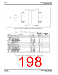
The HRTC Start Position and VRTC Start Position registers position the image horizontally
and vertically. The maximum and minimum register values for these registers are given in
Table 13-5: “Minimum and Maximum Values for NTSC/PAL”. Increasing the HRTC Start
Position will move the image left, while increasing the VRTC Start Position will move the
image up.
S1D13506
X25B-A-001-10
Hardware Functional Specification
Issue Date: 01/02/06

 EPSON [ EPSON COMPANY ]