EM78P809N
8-Bit Microcontroller
Table 2. Mode Switching Control
Mode Switch
Normal ꢃSleep
Sleep ꢃNormal
Normal ꢃIdle
Idle ꢃNormal
Switch Method
Set SIS = 1, execute SLEP instruction
/SLEEP pin wake up
Note
Set SIS = 0, execute SLEP instruction
Interrupt
Table 3. Operation Mode
On-chip
Operation Mode
Frequency
CPU Code
Peripherals
Reset
Reset
Fosc
Reset
Fosc
Halt
Turn on
Turn off
Normal
Idle
Signal
Clock
Halt
Sleep
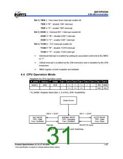
In NORMAL mode, the CPU core and on-chip peripherals operate in oscillator
frequency.
In IDLE mode, the CPU core halts, but the on-chip peripheral and oscillator circuit
remain active. IDLE mode is released to NORMAL mode by any interrupt source. If the
ENI instruction is set, an interrupt will be serviced first followed by executing the next
instruction which is after the IDLE mode is released and the interrupt service is finished.
If the ENI instruction is not set, the next instruction will be executed which is after the
IDLE mode start instruction. IDLE mode can also be released by setting the /RESET
pin to low and executing a reset operation.
In SLEEP mode, the internal oscillator is turned off and all system operation is halted.
SLEEP mode is released by /SLEEP pin (level sensitive or edge sensitive can be set by
System Control Register (SCR) bit 0 (REM)). After a warm-up period, the next
instruction will be executed which is after the SLEEP mode start instruction. SLEEP
mode can also be released by setting the /RESET pin to low and executing a reset
operation. In level sensitive mode, the /SLEEP pin must be confirmed in low level
before entering SLEEP mode. In edge sensitive mode, SLEEP mode is started even
when the /SLEEP pin is in high level.
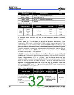
Table 4. Wake-up Methods
SLEEP Mode
IDLE Mode
NORMAL
Mode
Wake-up Signal
R5 (SIS) = 1+SLEP
Instruction
R5 (SIS)= 0 + SLEP
Instruction
R5 (SIS)=(*)
1. Individual interrupt source
in IMR1, IMR2
1. Wake-up
2. WDT interrupt request
3. /INT0
No effect
(**)
No effect
(**)
2. Jump to the next
instruction or enter
IDLE mode
4. ENI instruction is not
executed
28 •
Product Specification (V1.0) 07.26.2005
(This specification is subject to change without further notice)

 ELAN [ ELAN MICROELECTRONICS CORP ]