EM78P809N
8-Bit Microcontroller
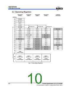
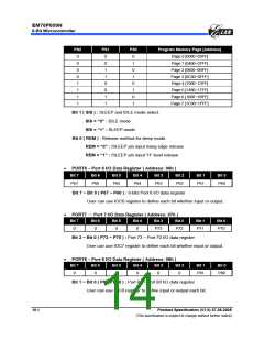
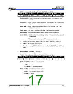
PS2
PS1
0
PS0
0
Program Memory Page [Address]
Page 0 [0000~03FF]
Page 1 [0400~07FF]
Page 2 [0800~0BFF]
Page 3 [0C00~0FFF]
Page 4 [1000~13FF]
Page 5 [1400~17FF]
Page 6 [1800~1BFF]
Page 7 [1C00~1FFF]
0
0
0
0
1
1
1
1
0
1
1
0
1
1
0
0
0
1
1
0
1
1
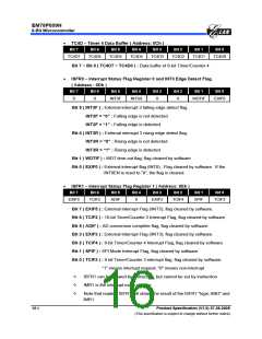
Bit 1 ( SIS ) : SLEEP and IDLE mode select.
SIS = “0” : IDLE mode
SIS = “1” : SLEEP mode
Bit 0 ( REM ) : Release method for sleep mode.
REM = “0” : /SLEEP pin input rising edge release
REM = “1” : /SLEEP pin input “H” level release
•
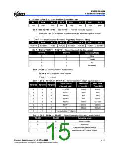
PORT6 − Port 6 I/O Data Register ( Address: 06h )
Bit 7
Bit 6
Bit 5
Bit 4
Bit 3
Bit 2
Bit 1
Bit 0
P67
P66
P65
P64
P63
P62
P61
P60
Bit 7 ~ Bit 0 ( P67 ~ P60 ) : 8-bits Port 6 I/O data register
User can use IOC6 register to define each bit whether input or output.
•
•
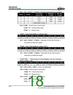
PORT7 — Port 7 I/O Data Register ( Address: 07h )
Bit 7
Bit 6
Bit 5
Bit 4
Bit 3
Bit 2
Bit 1
Bit 0
0
0
0
0
P73
P72
P71
P70
Bit 3 ~ Bit 0 ( P73 ~ P70 ) : Port 73 ~ Port 70 I/O data register
User can use IOC7 register to define each bit whether input or output.
PORT8 − Port 8 I/O Data Register ( Address: 08h )
Bit 7
Bit 6
Bit 5
Bit 4
Bit 3
Bit 2
Bit 1
Bit 0
0
0
0
0
0
0
P81
P80
Bit 1 ~ Bit 0 ( P81 ~ P80 ) : Port 81 ~ Port 80 I/O data register
User can use IOC8 register to define input or output each bit.
10 •
Product Specification (V1.0) 07.26.2005
(This specification is subject to change without further notice)

 ELAN [ ELAN MICROELECTRONICS CORP ]