EM78P809N
8-Bit Microcontroller
R5
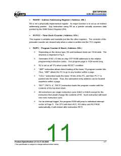
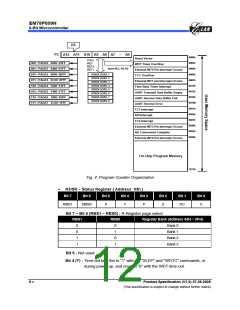
PC A12 A11 A10 A9 A8 A7
~
A0
0000h
0003h
0006h
0009h
000Fh
0012h
0015h
0018h
001Bh
0021h
0024h
0027h
0030h
0033h
0036h
Reset Vector
CALL
RET
000 : PAGE0 0000~03FF
WDT Timer Overflow
RETL
RETI
Store ACC, R3, R5
001 : PAGE1 0400~07FF
010 : PAGE2 0800~0BFF
011 : PAGE3 0C00~0FFF
100 : PAGE4 1000~13FF
101 : PAGE5 1400~17FF
110 : PAGE6 1800~1BFF
111 : PAGE7 1C00~1FFF
External INT0 Pin Interrupt Occurs
TCC Overflow
STACK LEVEL 1
STACK LEVEL 2
STACK LEVEL 3
STACK LEVEL 4
STACK LEVEL 5
STACK LEVEL 6
STACK LEVEL 7
STACK LEVEL 8
External INT1 pin Interrupt Occurs
Time Base Timer Interrupt
UART Transmit Data Buffer Empty
UART Receive Data Buffer Full
UART Receive Error
TC3 Interrupt
SPI Interrupt
TC4 Interrupt
External INT3 Pin Interrupt Occurs
AD Conversion Complete
External INT5 Pin Interrupt Occurs
On-chip Program Memory
1FFFh
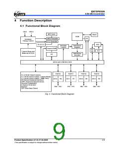
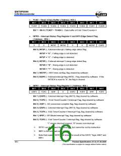
Fig. 4. Program Counter Organization
•
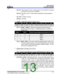
R3/SR − Status Register ( Address: 03h )
Bit 7
Bit 6
Bit 5
Bit 4
Bit 3
Bit 2
Bit 1
Bit 0
RBS1
RBS0
0
T
P
Z
DC
C
Bit 7 ~ Bit 6 (RBS1 ~ RBS0) : R-Register page select
RBS1
RBS0
Register Bank (Address 05H ~ 0FH)
0
0
1
1
0
1
0
1
Bank 0
Bank 1
Bank 2
Bank 3
Bit 5 : Not used
Bit 4 (T) : Time-out bit. Set to “1” with the "SLEP" and "WDTC" commands, or
during power up, and reset to “0” with the WDT time-out.
8 •
Product Specification (V1.0) 07.26.2005
(This specification is subject to change without further notice)

 ELAN [ ELAN MICROELECTRONICS CORP ]