EM78P341N/342N/343N
8-Bit Microprocessor with OTP ROM
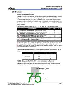
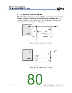
In most applications, Pin OSCI and Pin OSCO can be connected with a crystal or
ceramic resonator to generate oscillation. Fig. 6-18 below depicts such a circuit. The
same applies to the HXT1 mode, HTX2 mode, LXT1 mode and LXT2 mode.
C1
OSCI
Crystal
OSCO
RS
C2
Fig. 6-18 Crystal/Resonator Circuit
The following table provides the recommended values for C1 and C2. Since each
resonator has its own attribute, user should refer to the resonator specifications for the
appropriate values of C1 and C2. RS, a serial resistor, may be required for AT strip cut
crystal or low frequency mode.
Capacitor selection guide for crystal oscillator or ceramic resonators:
Oscillator Type
Frequency Mode
Frequency
C1 (pF)
C2 (pF)
455kHz
2.0 MHz
4.0 MHz
32.768kHz
100kHz
200kHz
455kHz
1.0 MHz
2.0 MHz
4.0 MHz
100~150
20~40
10~30
25
100~150
20~40
10~30
15
Ceramic Resonators
HXT
LXT
HXT
25
25
25
25
Crystal Oscillator
20~40
15~30
15
20~150
15~30
15
15
15
70 •
Product Specification (V1.0) 12.01.2006
(This specification is subject to change without further notice)

 ELAN [ ELAN MICROELECTRONICS CORP ]