EL4583C
Sync Separator, 50% Slice, S-H, Filter, H
OUT
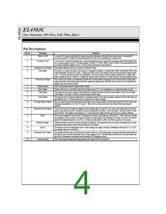
Pin Descriptions
Pin No.
Pin Name
Function
1
Filter Cut-Off
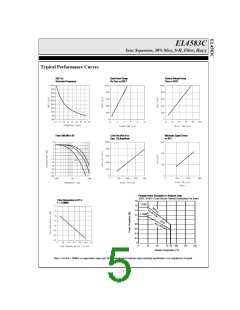
A resistor RF connected between this input and ground determines the input filter characteristic. Increasing RF
increases the filter 3.58MHz color burst attenuation. See the typical performance characteristics.
2
Set Detect Level
A resistor RLV connected between pin 2 and ground determines the value of the minimum signal which triggers the
loss of signal output on pin 10. The relationship is VPMIN = 0.75RLV/RSET, where VPMIN is the minimum detected
sync pulse amplitude applied to pin 4. See the typical performance characteristics.
3
4
Composite Sync Output
Filter Input
This output replicates all the sync inputs on the input video.
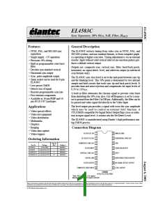
The filter is a 3 pole active filter with a gain of 2, designed to produce a constant phase delay of nominally 260ns with
signal amplitude. Resistor RF on pin 1 controls the filter cut-off. An internal clamp sets the minimum voltage on pin
4 at 1.55V when the input becomes low impedance. Above the clamp voltage, an input current of 1µA charges the
input coupling capacitor. With loss of signal, the current source switches to a value of 10µA, for faster signal recovery.
5
Vertical Sync Output
The vertical sync output is synchronous with the first serration pulse rising edge in the vertical interval of the input
signal and ends on the trailing edge of the first equalizing Output pulse after the vertical interval. It will therefore be
slightly more than 3H lines wide.
6
7
8
Digital Ground
Filter Output
Video Input
This is the ground return for digital buffer outputs.
Output of the active 3 pole filter which has its input on pin 4. It is recommended to ac couple the output to pin 8.
This input can be directly driven by the signal if it is desired to bypass the filter, for example, in the case of strong
clean signals. This input is 6dB less sensitive than the filter input.
9
Level Output
This pin provides an analog voltage which is nominally equal to twice the sync pulse amplitude of the video input sig-
nal applied to pin 4. It therefore provides an indication of signal strength.
10
No Signal Detect Output
This is a digital output which goes high when either a) loss of input signal or b) the input signal level falls below a pre-
determined amplitude as set by RLV on pin 2. There will be several horizontal lines delay before the output is
initiated.
11
12
Burst/Back Porch Output
RSET
The start of back porch output is triggered on the trailing edge of normal H sync, and on the rising edge of serration
pulses in the vertical interval. The pulse is timed out internally to produce a one-shot output. The pulse width is a func-
tion of RSET. This output can be used for d.c. restore functions where the back porch level is a known reference.
The current through the resistor RSET determines the timing of the functions within the I.C. These functions include
the sampling of the sync pulse 50% point, back porch output and the 2H eliminator. For faster scan rates, the resistor
needs to be reduced inversely. For NTSC 15.7kHz scan rate RSET is 681k 1%. RSET must be a 1% resistor.
13
14
15
Odd/Even Output
VDD 5V
Odd-even output is low for even field and high for odd field. The operation of this circuit has been improved for reject-
ing spurious noise pulses such as those present in VCR signals.
The internal circuits are designed to have a high immunity to supply variations, although as with most I.C.s a 0.1µF
decoupling capacitor is advisable.
Horizontal Sync Output
This output produces only true H pulses of nominal width 5µs. The leading edge is triggered from the leading edge of
the input H sync, with the same prop. delay as the composite sync. The half line pulses present in the input signal dur-
ing vertical blanking are eliminated with an internal 2H eliminator circuit.
16
Analog Ground
This is the ground return for the signal paths in the chips, RSET, RF and RLV.
4

 ELANTEC [ ELANTEC SEMICONDUCTOR ]