AZ431-A
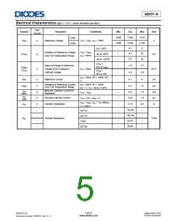
Electrical Characteristics (@TA = +25°C, unless otherwise specified.)
Test
Symbol
Parameter
Conditions
Min
Typ
Max
Unit
Circuit
2.490
2.480
–
2.500
2.500
4.5
2.510
2.520
8
0.4%
0.8%
VREF
4
Reference Voltage
VKA = VREF, IKA = 10mA
V
0 to +70oC
Deviation of Reference Voltage
Over Full Temperature Range
VKA = VREF
IKA = 10mA
–
4.5
10
VREF
4
5
-40 to +85oC
-40 to +125oC
mV
4.5
–
–
16
VKA
10V to VREF
VKA
36V to 10V
=
-1.0
-0.5
-2.7
Ratio of Change in Reference
Voltage to the Change in
Cathode Voltage
VREF
VKA
IKA = 10mA
mV/V
=
–
-2.0
IKA = 10mA, R1 = 10KΩ, R2 =
∞
IREF
5
5
Reference Current
–
–
0.7
0.4
4
µA
µA
Deviation of Reference Current
Over Full Temperature Range
IKA = 10mA, R1 = 10KΩ
R2 = ∞, TA = -40 to +125oC
1.2
IREF
Minimum Cathode Current for
Regulation
IKA
(Min)
4
6
–
–
0.4
1.0
1.0
mA
µA
VKA = VREF
IKA
(Off)
Off-state Cathode Current
0.05
VKA = 36V, VREF = 0
VKA = VREF, IKA = 1 to 100mA,
4
Dynamic Impedance
–
0.15
0.5
Ω
ZKA
f ≤ 1.0KHz
–
–
–
–
–
–
–
–
135.48
135.48
81.63
–
–
–
–
SOT23
SOT25
TO92
Thermal Resistance
oC/W
θJC
29.80
SOT89
5 of 21
www.diodes.com
September 2015
© Diodes Incorporated
AZ431-A
Document number: DS36721 Rev. 5 - 2

 DIODES [ DIODES INCORPORATED ]