AZ431-A
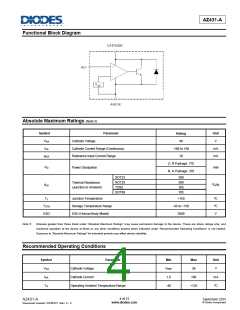
Functional Block Diagram
Absolute Maximum Ratings (Note 5)
Symbol
Parameter
Unit
V
Rating
40
VKA
IKA
Cathode Voltage
Cathode Current Range (Continuous)
Reference Input Current Range
-100 to 150
10
mA
mA
IREF
Z, R Package: 770
N, K Package: 370
PD
Power Dissipation
mW
SOT23
380
380
165
165
SOT25
TO92
Thermal Resistance
(Junction to Ambient)
θJA
oC/W
SOT89
TJ
Junction Temperature
+150
-65 to +150
2000
ºC
ºC
V
TSTG
ESD
Storage Temperature Range
ESD (Human Body Model)
Note 5:
Stresses greater than those listed under “Absolute Maximum Ratings” may cause permanent damage to the device. These are stress ratings only, and
functional operation of the device at these or any other conditions beyond those indicated under “Recommended Operating Conditions” is not implied.
Exposure to “Absolute Maximum Ratings” for extended periods may affect device reliability.
Recommended Operating Conditions
Symbol
Parameter
Min
VREF
1.0
Max
36
Unit
V
VKA
IKA
TA
Cathode Voltage
Cathode Current
100
+125
mA
ºC
Operating Ambient Temperature Range
-40
4 of 21
www.diodes.com
September 2015
© Diodes Incorporated
AZ431-A
Document number: DS36721 Rev. 5 - 2

 DIODES [ DIODES INCORPORATED ]