AP431/AP431A
ADJUSTABLE PRECISION SHUNT REGULATOR
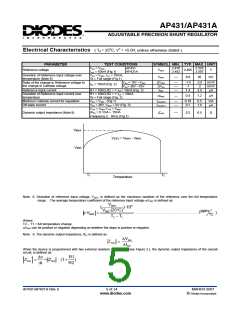
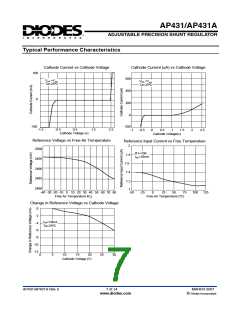
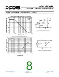
Typical Performance Characteristics ( Continued )
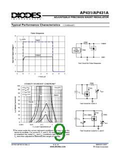
Pulse Response
Input
6
5
4
3
2
1
0
TA=25oC
220Ω
Output
Pulse
Generator
f=100kHz
50Ω
Output
GND
Test Circuit for Pulse Response
-1
0
1
2
3
4
5
6
7
t-Time-µS
150Ω
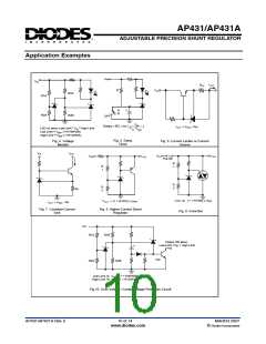
STABILITY BOUNDARY CONDITIONS†
100
TA=25oC
AVKA=V
ref
I
KA
90
80
70
60
50
40
30
20
10
0
B VKA=5V
+
-
VBATT
C VKA=10V
D VKA=15V
CL
B
Stable
C
Stable
Test Circuit for Curve A
A
D
I
KA
150Ω
R1=10KΩ
CL
+
-
R2
VBATT
0.001
0.01
0.1
1
10
CL-Load Capacitance-µF
The areas under the curves represent conditions that may cause the
device to oscillate. For curves B, C, and D, R2 and V+ were adjusted
to establish the initial VKA and IKA conditions with CL=0.VBATT and
CL were then adjusted to determine the ranges of stability.
Test Circuit for Curve B, C, and D
AP431/AP431A Rev. 5
9 of 14
MARCH 2007
www.diodes.com
© Diodes Incorporated

 DIODES [ DIODES INCORPORATED ]