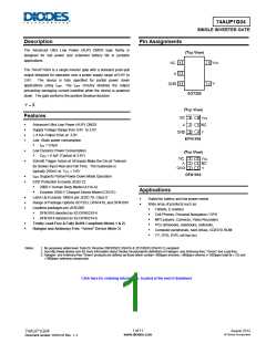
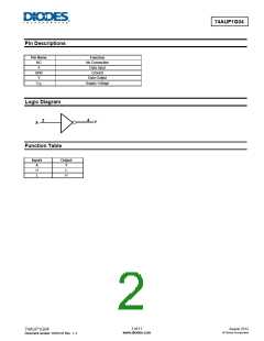
74AUP1G04
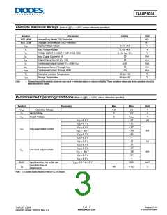
Absolute Maximum Ratings (Note 4) (@TA = +25°C, unless otherwise specified.)
Symbol
ESD HBM
ESD CDM
VCC
Parameter
Human Body Model ESD Protection
Rating
Unit
KV
KV
V
2
Charged Device Model ESD Protection
Supply Voltage Range
1
-0.5 to +4.6
-0.5 to +4.6
Input Voltage Range
V
VI
Voltage applied to output in high or low state
Input Clamp Current VI <0
V
Vo
IIK
-0.5 to VCC +0.5
50
50
mA
mA
IOK
IO
Output Clamp Current (VO < 0 )
±20
mA
mA
mA
°C
Continuous Output Current (VO = 0 to VCC
Continuous Current Through VCC
Continuous Current Through GND
Operating Junction Temperature
Storage Temperature
)
50
ICC
IGND
TJ
-50
-40 to +150
-65 to +150
°C
TSTG
Note:
4. Stresses beyond the absolute maximum may result in immediate failure or reduced reliability. These are stress values and device operation should be
within recommend values.
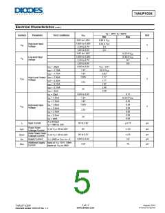
Recommended Operating Conditions (Note 5) (@TA = +25°C, unless otherwise specified.)
Symbol
VCC
VI
Parameter
Min
0.8
0
Max
3.6
3.6
VCC
-20
-1.1
-1.7
-1.9
-3.1
-4
Unit
V
Operating Voltage
Input Voltage
V
Output Voltage
0
V
VO
µA
VCC = 0.8 V
VCC = 1.1 V
VCC = 1.4 V
VCC = 1.65 V
VCC = 2.3 V
VCC = 3.0 V
VCC = 0.8 V
VCC = 1.1 V
VCC = 1.4 V
VCC = 1.65 V
VCC = 2.3 V
VCC = 3.0 V
VCC = 0.8 V to 3.6 V
High-level output current
IOH
mA
uA
20
1.1
1.7
1.9
3.1
4
Low-level output current
IOL
mA
Δt/ΔV
Input transition rise or fall rate
200
ns/V
°C
Operating free-air
temperature
-40
+125
TA
Note: 5. Unused inputs should be held at VCC or Ground.
3 of 11
www.diodes.com
August 2012
© Diodes Incorporated
74AUP1G04
Document number: DS35147 Rev. 1- 2

 DIODES [ DIODES INCORPORATED ]